1998 JAGUAR X308 checking oil
[x] Cancel search: checking oilPage 39 of 2490

Before inspecting a component for wear or per
forming a dimensional check,
ensure that it is absolutely clean; a slight smear
of grease can conceal an incipient failure. When a component is to be checked dimensionally against figures quoted for it,
use the correct equipment (surface plates, micrometers, dial gauges etc.) in serviceable condition. The use of makeshift
equipment can be dangerous. Reject a component if its dimensio ns are outside the limits quoted, or if damage is apparent.
A part may be refitted if its critical di mension is exactly to the limit size and it is otherwise satisfactory. Use Plastigauge 12
Type PG-1 for checking bearing surface clearance, e.g. big end bearing shell to crank jour nal. Instructions for the use of
Plastigauge and a scale giving bearing clearances in steps of 0.0025 mm (0.0001 in) are supplied with the package.
Safety
Precautions
• WAR
NINGS:
WORKING ON THE FUEL SYSTEM RESULTS IN FUEL AND FUEL VAPOUR BEING PRESENT IN THE ATMOSPHERE. FUEL
VAPOUR IS EXTREMELY FLAMMABLE, HENCE GREAT CARE MUST BE TAKEN WHILST WORKING ON THE FUEL SYSTEM.
ADHERE STRICTLY TO THE FOLLOWING PRECAUTIONS:
DO
NOT SMOKE IN THE WORK AREA.
DISP
LAY 'NO SMOKING' SIGNS AROUND THE AREA.
DISCONNECT TH
E BATTERY BEFORE WORKING ON THE FUEL SYSTEM.
DO NOT CONNEC
T/DISCONNECT ELECTRICAL CIRCUITS
, USE ELECTRICAL EQUIPMENT OR OTHER TOOLS OR
ENGAGE IN WORKING PRACTICES WHICH IN ANY WAY MAY RESULT IN THE PRODUCTION OF SPARKS.
ENS
URE THAT A CO2 FIRE EXTINGUISHER IS CLOSE AT HAND.
ENS
URE THAT DRY SAND IS AVAILABLE TO SOAK UP ANY FUEL SPILLAGE.
EMP
TY FUEL USING SUITABLE FIRE PROOF EQUIPMENT IN
TO AN AUTHORIZED EXPLOSION PROOF CONTAINER.
DO NOT EMP
TY FUEL WHILE WORKING IN A WORKSHOP OR A PIT.
ENS
URE THAT WORKING AREA IS WELL VENTILATED.
ENS
URE THAT ANY WORK ON THE FUEL SYSTEM IS ON
LY CARRIED OUT BY EXPERIENCED AND WELL QUALIFIED
MAINTENANCE PERSONNEL.
ENS
URE THAT FUME EXTRACTION EQUIPMENT IS USED WHERE APPROPRIATE.
FUME EXTRACTION EQUIPMENT MUST BE IN OPERATION WHEN SOLVENTS ARE USED E.G. TRICHLOROETHANE,
WHITE SPIRIT, SBP3, METHYLENE CHLORIDE, PERCHLORETHY LENE. DO NOT SMOKE IN THE VICINITY OF VOLATILE
DEGREASING AGENTS.
General workshop practices:
Disc
onnect the grounded termin
al of the vehicle battery.
D
o not apply heat in an attempt to free seized nuts or fitt
ings; as well as causing damage to protective coatings,
there is a risk of damage from stray heat to electronic equipment and brake lines.
Keep oils and solven
ts away from naked flames and other sour
ces of ignition.
Adhere str
ictly to handling and safety inst
ructions given on containers and labels.
E
nsure that a suitab
le form of fire extinguisher is conveniently located.
Wh
en using electrical tools and equipment, inspect the power
lead for damage and check that it is properly earthed.
D
o not leave tools, equipment, spilt oil etc. around the work area.
Working beneath a vehicle:
Wh
enever possible, use a ramp or
pit in preference to jacking.
Posit
ion chocks at the wheels as we
ll as applying the parking brake.
N
ever rely on a jack alone to support a
vehicle; use axle stands, or blocks care fully placed at the jacking points, to
provide a rigid location.
Ch
eck that any lifting equipment used has adeq
uate capacity and is fully serviceable.
Working on air conditioning systems:
D
o not disconnect any pipes of the refrigeration system
unless you are trained and instructed to do so; a refrigerant
is used which can cause blindness if allowed to come into contact with the eyes.
Health Protection
P
rolonged and repeated contact with mineral oil will result in the removal of natural oils from the skin, leading to dryness,
In
spection
Page 1262 of 2490
Contains th
e hydraulic system pump.
Contains
th
e fluid temperature sensor.
The epicyclic geartrain:
Provi des fi
ve forward gears and Reverse.
Has
h
ydraulically actuated, multi-disk clutches, to select the required gear ratios.
Feature
s clutch-to-clutch operation to permit
gear shifts for uninterrupted power flow.
The electro-hydraulic control unit:
Is lo c
ated in the lower part of
the unit, within the fluid pan.
Is controlled
by the TCM (transmissio
n control module), and the manual selector valve which is cable operated.
Re
gulates the flow of fluid to the ge
artrain clutches via three solenoid-operated valv es and the manual selector
valve.
Has fi ve pressure
regulators for controll
ing fluid pressures within the system.
Is con
nected to the TCM via a 16-way connector mounted on
the left-hand side of the transmission casing. Refer to
Connector Pins Identification, Section 307-01A.
The hydraulic system pump:
Is l o
cated at the front of the transmission casing.
Is dri
v
en from the impeller hub,
pressurising the fluid whenever the engine is running.
Supplie
s fluid under pressure to the torq
ue converter, geartrain, electro-hydr aulic control unit and the lubrication
circuit.
D r
aws fluid from the fluid pa
n below the transmission casing, through a filter.
The rear extension housing:
Is bolt
ed to the rear of the transmission casing.
Provides the rear engine / transmi
ssion mo
unting point; refer to section 303-01.
Carrie
s the transmission output shaft oil seal.
Filled-for-l
i
fe Fluid System
The
transm
ission is 'filled for life' and
does not require fluid changes, except where extreme driving conditions prevail.
Routine level checking is not required and a dipstick is not pr ovided. A level / filler plug is fitted for level checking and
replenishment, following service actions; see 303-01 General Procedures.
Transmission Torque Converter
Page 1270 of 2490
1.1. The hydraulic system has 'fail-safe' characteristics regardin g its electrical operation, such that should the power
supply be lost to the electro-hydraulic actuators the transmission will initiate a limp-home mode.
2. 2. Recognition of critical shift operation by monitoring the last element in the signal path, ie the solenoid valve, and
checking by means of redundant me asured variables, ie engine speed, input speed and output speed.
3. 3. Each time the vehicle is started there is a check on the entire safety hardware and the associated program parts
and signal paths. A malfunction in this part of the system, or triggering of the safety circuit, is communicated to
the operator through the illumination of the transmission warning lamp.
TCM Inputs
Input Speed Sensor (Torque Converter Turbine)
The input speed sensor provides the TCM with transmission inpu t shaft speed information. This signal is produced from an
inductive pick-up, generating 30 pulses per revolution.
Transmission Output Speed Sensor
The output speed sensor provides the TCM with transmission ou tput shaft speed information. This signal is produced from
an inductive pick-up, generati ng 36 pulses per revolution.
Transmission Oil Temperature Sensor
A thermistor which provides an electrical indication of the oi l temperature to the TCM. The signal is measured as a voltage
with reference to analog ue ground in the TCM.
Kickdown Switch (where fitted)
Kickdown is intended to provide maximum vehicle acceleration , via the appropriate downshift(s), when the operator uses
full throttle. A kickdown switch provides an electrical signal to the TCM wh en the accelerator pedal is fully pressed. The
switch is normally open, connected to vehicle ground. Should the switch fail the TCM will detect kickdown using the
accelerator pedal position.
Throttle Pedal Stop (where fitted)
This component, used where the kickdown switch is not fitted, limits throttle pedal travel .in the same way. The kickdown
feature is retained, but is controlled by throttle position only. The pedal stop must be set, using the PDU, in the same way
as the kickdown switch to optimize performance.
Mode Selection Switch
The mode selection switch is a two position switch indicati ng to the TCM the current performance mode selected by the
driver. The switch generates a tw o-bit digital input to the TCM.
Rotary Position Switch
The rotary position switch detects the position of the transmis sion selector shaft. The switch is supplied as part of a new
transmission assembly, mounted on the transmission body. The swit ch is used to indicate to the TCM the six positions of the shaft: Park, Reverse, Neutral, Drive, Third and Second. The switch provides a four-bit input to the TCM.
Drive to Fourth Switch
Detects the movement of the selector lever from Drive to Fourth position. The selector cable, and therefore the transmission selector shaft, does not move as the lever is operated between these two positions. The switch is located within the 'J-gate'
assembly, producing a digital output to indicate to the TCM that the lever has moved from D to 4 .
Serial Communications Interfaces
Page 1883 of 2490
Belt tension is achieved by an automatic tensioner; neither the belt nor the tensioner require service apart from checking
the belt wear indicators at each normal service interval.
The minimum service life of the drive belt is 100,000 miles.
Never apply oil to the belt or to the belt tensioner.
Generator - Charging Circuit
Parts List
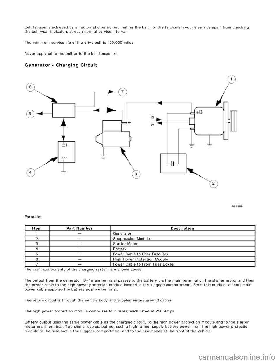
The main components of the charging system are shown above.
The output from the generator 'B+' main te rminal passes to the battery via the main terminal on the starter motor and then
the power cable to the high power protection module located in the luggage compartment. From this module, a short main
power cable supplies the ba ttery positive terminal.
The return circuit is through the vehicle body and supplementary ground cables.
The high power protection mo dule comprises four fuses, each rated at 250 Amps.
Battery output uses the same power cable as the charging circ uit, to the high power protection module and to the starter
motor main terminal. Two similar cables, but not such a high rating, supply battery power from the high power protection
module to the fuse box in the luggage compartment an d to the fuse boxes at the front of the vehicle.
ItemPart NumberDescription
1—Generator
2—Suppression Module
3—Starter Motor
4—Battery
5—Power Cable to Rear Fuse Box
6—High Power Protection Module
7—Power Cable to Front Fuse Boxes
Page 1886 of 2490
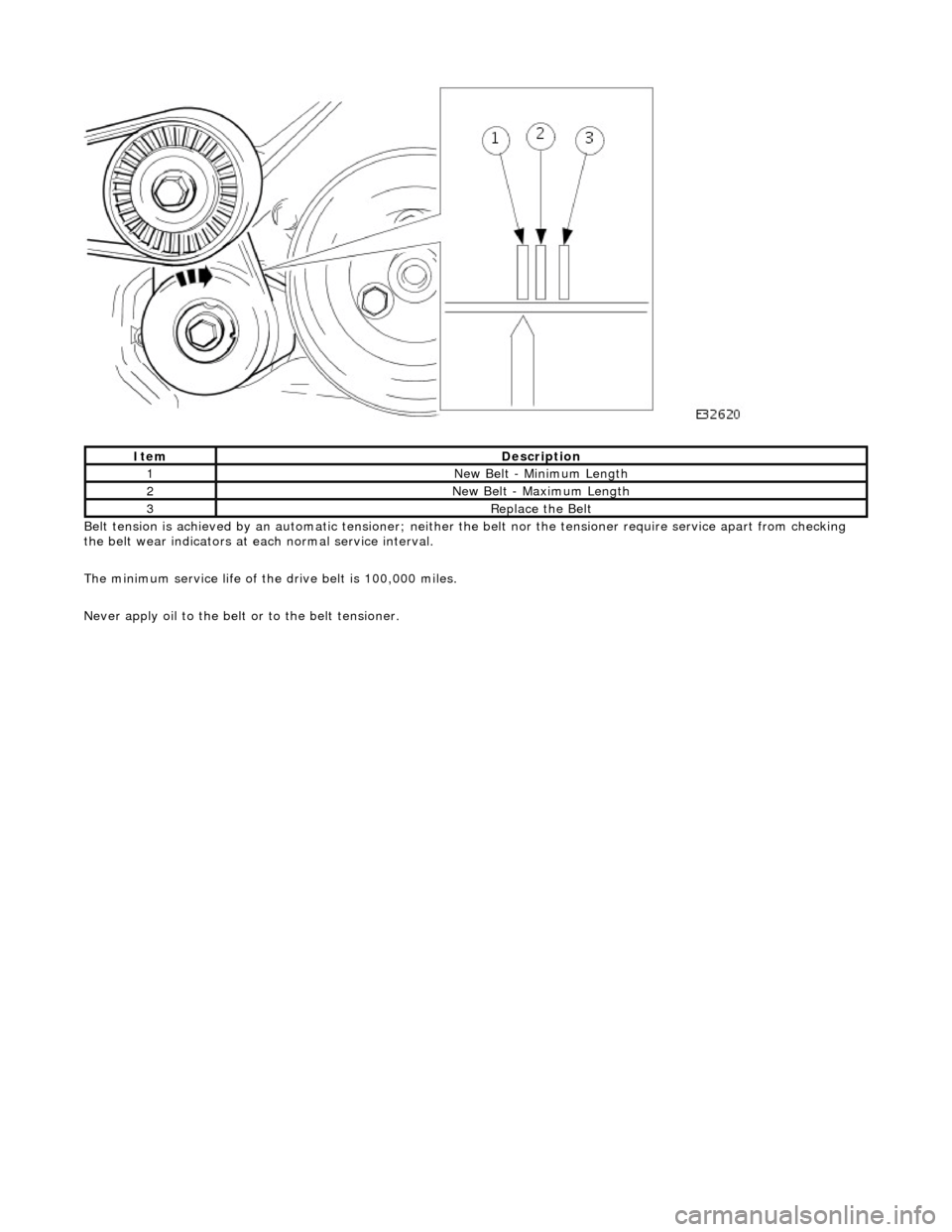
Belt tension is achieved by an automatic tensioner; neither the belt nor the tensioner require service apart from checking
the belt wear indicators at each normal service interval.
The minimum service life of the drive belt is 100,000 miles.
Never apply oil to the belt or to the belt tensioner.
ItemDescription
1New Belt - Minimum Length
2New Belt - Maximum Length
3Replace the Belt
Page 2381 of 2490
The body is pre-treated to ensure high resistance to corrosion and stone chip dama ge. Prior to the first major pre-treatment process, the body shell is high-pressure washed to remove any metal dust and residual oil.
The first major pre-treatment process consists of phosphate and electro-paint deposition, which together with zinc coating,
forms the basis of the corrosion protection. This process includes high pressure knock-off, alkali de-greasing, zinc phosphate
conversion of body steel (dissolving iron and coating with zinc phosphate crystals), trivalent chrome rinsing and
demineralized water rinsing, seal ing all chemicals and impurities.
Both dip and spray techniques are employed and the bodies are submerged to the waistline during the first and third rinses
of the main phosphate clean. Chemical strengths and soluti on temperatures are continuously monitored and accurately
controlled throughout the process.
An 80% water primer is then cathodic elec tro-deposition applied to the thoroughly cleansed bodies in a uniform 'sag-free'
film 18 to 32 micron thick. Optimum durabi lity of the electroprimer is achieved by finally curing in a stoving oven at 165 °C
for a period of 20 minutes.
All underbody seams of the fully primed bo dies are then manually sealed, to prevent water and dust ingress into the vehicle
and to enhance corrosion protection.
An 800 to 1000 g/m2 PVC coating is semi-automatic airless sp ray applied to the underside of the main floor panels, trunk
floor and rear wheel arches (ref. illustration above).
The upper panels of primed and external ly sealed bodyshells are next lightly scuffed to remove imperfections and a PVC
coating is applied to all internal seams by an airless spray technique. A PVC bead seal is also applied to the doors, hood and
trunk clinch joints.
Following anti-corrosion, sealing and primin g treatment, the bodies enter the first stage of 'cosmetic' painting. This consists
of the application of two coats of a highly chip resistant po lyester surfacer, employing high voltage electrostatic 'spinning
bells', to achieve a final film thickness of 35 to 50 micron. Between surfacer coats, a polyurethane coat is automatically
applied to the sills to impart even greater resistance to stone chipping.
All interior panels are then painted us ing a color keyed sealer, wet-on-wet wi th a surfacer material, after which the
bodyshells are stoved at 160 °C for a period of 20 minutes. Further protection agai nst corrosion is provided by a medium
solids black pigmented wax which is airless spray applied to vehicle undersides.
Wax Injected Box Sections
Critical body box-sections are si milarly protected by spray injecting a high solids wax. This is then re-flowed at 70 to 90 °C
to achieve optimum seam/joint penetratio n and form a resilient and durable internal coating (ref. illustration above).
After full wet sanding, rinsing and drying to provide a good su bstrate, a color-keyed semi-matt sealer co at is applied using
electrostatic bells to achieve a film build of 25 to 35 micron . The bodies are then stoved for a further 20 minutes at a
temperature of 145 °C and subjected to a local 'seek-and-find' de -nib operation prior to the final two coat process. The final
top coat finish is achieved by using poly ester base coat colors and an acrylic sag resistant clear coat. This clear over base
(COB) process produces a high gloss, durabl e paint finish with a film thickness of 50 to 65 micron, which is finally cured at a
temperature of 135°C for 20 minutes.
The Munsell three dimensional system of color management is em ployed to achieve highly accurate control of vehicle colors.
This system ensures that paint pigmentations are accurately maintained and facilitates vigorous final checking of finished
vehicles for color match. The hu e of individual panels such as trunk lids, doors and hoods is in some instances adjusted to
offset the effects of differing light angles. Where applicable, coachlines are manually applied and radiant heat cured on the
completed and valeted vehicle prior to hand spray applic ation of a protective wax coat.
Introduction
All repairs, whether structural or cosmetic must return the vehicle to the original manufactured condition with regard to
occupant safety, dimensional accuracy, fi nish and corrosion protection, and ensure continuation of the Paint Surface and
Corrosion warranty where applicable.
Similarly, repaired vehicles must be fu lly checked, and where appropriate reset, with regard to steering, suspension,
braking, and occupant restraint systems.