Page 1922 of 2490

Exterior Lighting - Exterior Lighting
Diagnosis and Testing
Tests Using the Portable Diagnostic Unit
Refer to PDU User Guide
The complexity of the electronics involved with the various Electronic Control Modules and the multiplexed communication
networks, preclude the use of workshop general electrical test equipment. Therefore, reference should be made to the PDU
User Guide for detailed inst ructions on testing the exterior lamps and circuits.
The PDU systematically tests and analyses the lamp assemblies, the bulbs and the electrical connections to them. It should
be noted that the lamps are not wired direct ly to the switches. Actuation of a switch provides an input signal to the Body
Processor which interpre ts the signal as a request to switch output from the Bo dy Processor, either directly or indirectly to a
specific lamp.
Where a fault involving a lamp is indicated by the PDU, befo re replacing the component, some basic diagnostic methods
may be necessary to confirm that connections are good and that wiring is not damaged.
Page 1940 of 2490
Exterior Lighting - High Mounted Stoplamp
Removal and Installation
Removal
Installation
1. Remove lamp cover.
1. Depress two tangs at base of lamp carrier and withdraw cover.
2. Disconnect lamp harness connector.
3. Remove module.
1. Release spring clips at each end of lamp lens module and withdraw module from carrier.
4. Remove lamp carrier.
Release lamp carrier lower securing tangs.
Slide carrier upwards to release and remove carrier from
backlight.
1. Ensure that rubber insulating pads are installed on lamp
carrier.
Page 1941 of 2490
2. Install lamp carrier on backligh t mountings, ensuring retaining
tangs seat correctly.
3. Install lamp module.
1. Slide lamp module into ca rrier ensuring retaining clips
seat correctly.
4. Connect harness connector to lamp assembly.
5. Install cover on lamp ensuring ta ngs locate correctly in carrier.
Page 1943 of 2490
Exterior Lighting - High Mounted Stoplamp Bulb
Removal and Installation
Removal
Installation
1. Remove cover from stop lamp.
1. Depress two tangs at base of lamp cover and withdraw cover.
2. Remove lamp module.
1. Release spring clips at each end and remove lamp module from carrier.
3. CAUTION: Exercise care to avoid contact with reflective
surfaces.
Withdraw lens and remove re levant bulb from module.
1. CAUTION: Exercise care to avoid contact with reflective
surfaces.
Install new bulbs as nece ssary and install lens.
2. Install module.
1. Slide module into carrier and seat securing clip at
Page 1962 of 2490

Interior Lighting - Interior Lighting
Description and Operation
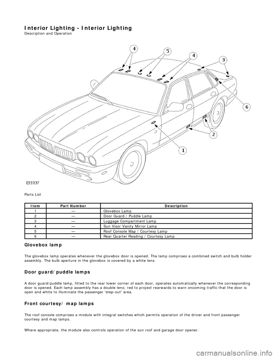
Parts List
Glovebox lamp
The glovebox lamp operates whenever the glovebox door is opened. The lamp comprises a combined switch and bulb holder assembly. The bulb aperture in the glovebox is covered by a white lens.
Door guard/puddle lamps
A door guard/puddle lamp, fitted to the rear lower corner of each door, operates automatically whenever the corresponding
door is opened. Each lamp assembly has a double lens; red to project rearwards to warn oncoming traffic that the door is
open and white to illuminate the passenger 'step-out' area.
Front courtesy/ map lamps
The roof console comprises a module with integral switches which permits operation of the dr iver and front passenger
courtesy and map lamps.
Where appropriate, the module also controls operation of the su n roof and garage door opener.
ItemPart NumberDescription
1—Glovebox Lamp
2—Door Guard / Puddle Lamp
3—Luggage Compartment Lamp
4—Sun Visor Vanity Mirror Lamp
5—Roof Console Map / Courtesy Lamp
6—Rear Quarter Reading / Courtesy Lamp
Page 1963 of 2490

Rear courtesy/ reading lamps
Each rear quarter of the passenger compartment is fitted with combined lighting units comprising; a rear courtesy lamp and
reading lamp. The courtesy lamps operate automatically whenever a rear door is opened; the reading lamps function when
the integral switches are operated by occupants of the vehicle.
Trunk lamps
The trunk trim panel is fitted with lamps which operate auto matically whenever the trunk lid is opened; the switch is
incorporated within the latch mechanism.
Vanity mirror lamps
The vanity mirror lamps, two on each sun visor, operate auto matically when the mirror flap is opened, provided the sun
visor spindle is engage d in the stowage clip.
Operation
The BPM provides an enable signal for the glovebox, vanity mirror, trunk lid and map lamps. Actuation of the relevant
switch provides an earth path to the lamp.
The rear passenger reading lamps receive a supply di rect from fuse F10 in the RH heelboard fuse-box.
The front and rear courtesy lamps have separa te fade functions controlled by the BPM.
The door hazard / puddle lamps are controll ed locally by the relevant Door Module.
Fault analysis must be undertaken using the PDU, refer to Diagnosis and Testing.
Refer to the relevant Electrical Guid e for details of circuit operation.
Page 1964 of 2490

Interior Lighting - Interior Lighting
Diagnosis and Testing
Tests Using the Portable Diagnostic Unit
Refer to PDU User Guide
The complexity of the electronics involved with the various Electronic Control Modules and the multiplexed communication
networks, preclude the use of workshop general electrical test equipment. Therefore, reference should be made to the PDU
User Guide for detailed inst ructions on testing the interior lamps and circuits.
The PDU systematically tests and analyses the lamp assemblies, the bulbs and the electrical connections to them. It should
be noted that the lamps are not wired directly to the switches.
The lamps are controlled directly by the Bo dy Processor (it has a sufficient number of high power output stages to drive the
lamps / relays compared to other module s) except for the door guard / puddle lamps and the rear passenger reading lamps.
The Body Processor Module receives messages on the SCP network from the door modules relating to door ajar / closed /
locked status, sensed by the door courtesy switch(es).
Where a fault involving a lamp is indicated by the PDU, be fore replacing suspect components, some basic diagnostic
methods may be necessary to confirm that connecti ons are good and that wiring is not damaged.
Page 1973 of 2490
Module Communications Network - Communications Network
Description and Operation
Fuse Boxes and Relays (LH Steering)
Parts List
There are six fuse box assemblies per vehicle, five of which have conventional, replaceable fuses. The High Power Protection
Module does not have conventional fuses, it comprises three 250 Amp fusible links to protect the starting circuit (two
connected in parallel) and the battery positive supply to the other fuse boxes.
Wiring Harnesses
ItemPart NumberDescription
1—Engine and Transmission Cont rol Module Compartment Relays (RH Steering opposite)
2—Front Firewall Relays
3—Front Seat Relays - Right Hand Side
4—Heelboard - Right Hand Side
5—High Power Protection Module
6—Trunk Fuse Box
7—Heelboard - Left Hand Side
8—Front Seat Relays - Left Hand Side
9—Engine Management Fuse Box
10—Engine Compartment Fuse Box
11—Engine Compartment Front Relays