Page 1744 of 2490

Speed Control - Speed
Control
D
iagn
osis and Testing
Pri
n
ciples of operation
The s
p
eed (cruise) control sy
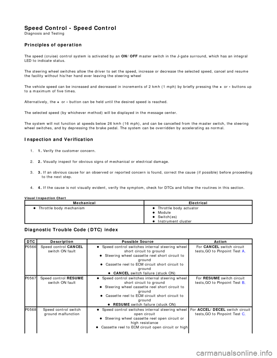
stem is activated by an ON/OFF master switch in the J-gate surround, which has an integral
LED to indicate status.
The steering wheel switches allow the driver to set the speed, increase or decrease the selected speed, cancel and resume
the facility without his/her hand ever leaving the steering wheel
The vehicle speed can be increased an d decreased in increments of 2 kmh (1 mph) by briefly pressing the + or - buttons up
to a maximum of five times.
Alternatively, the + or - button can be held until th e desired speed is reached.
The selected speed (by whichever method) w ill be displayed in the message center.
The system will not function at speeds below 26 kmh (16 mph), and can be cancelled from the master switch, the steering
wheel switches, and by depressing th e brake pedal. The system can be overridden by accelerating as normal.
In
spection and Verification
1.
1. Veri fy the customer concern.
2. 2. Vis
ually inspect for obvious signs of mechanical or electrical damage.
3. 3. If an obvious cause for an observed or reported concern is found, correct the cause (if possible) before proceeding
to the next step.
4. 4. If the cause is not visually evident, verify the symptom, check for DTCs and follow the routines in this section.
Vi
sual Inspection Chart
Diagnostic Trouble Code (D
TC) index
MechanicalElectrical
Throttle body mechan
ism
Throttle body actuator
Module Switch(es) Instrument cluster
DTC
De
scr
iption
Possib
l
e Source
Acti
o
n
P0566Speed
c
ontrol
CANCEL
switch ON fault
Speed
control switches internal steering wheel
short circuit to ground
St
eering wheel cassette reel short circuit to
ground
Cassette reel to ECM circ
uit short circuit to
ground
CANCEL
switch failure (stuck ON)
Fo
r
CANCEL switch circuit
tests,GO to Pinpoint Test A.
P0567Speed c
ontrol
RESUME
switch ON fault
Speed
control switches internal steering wheel
short circuit to ground
St
eering wheel cassette reel short circuit to
ground
Cassette reel to ECM circ
uit short circuit to
ground
RESUME swit
ch failure (stuck ON)
For
RESUME switch circuit
tests,GO to Pinpoint Test B.
P0568Spee
d control switch
ground malfunction
Speed
control switches internal steering wheel
open circuit
St
eering wheel cassette reel open circuit or
high resistance
Cassette reel to ECM ci
rcuit open circuit or high
For
ACCEL/DECEL switch circuit
tests,GO to Pinpoint Test C.
Page 1777 of 2490

Air Distribution and Filtering - Center Registers
Removal and Installation
Removal
Installation
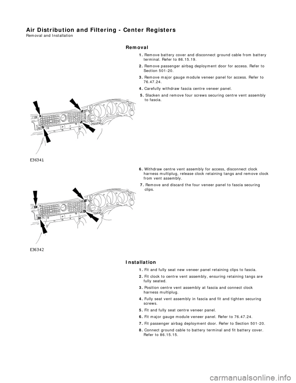
1.
Remove battery cover and disconnect ground cable from battery
terminal. Refer to 86.15.19.
2. Remove passenger airbag deployment door for access. Refer to
Section 501-20.
3. Remove major gauge module veneer panel for access. Refer to
76.47.24.
4. Carefully withdraw fascia centre veneer panel.
5. Slacken and remove four screws securing centre vent assembly
to fascia.
6. Withdraw centre vent assembly for access, disconnect clock
harness multiplug, release clock retaining tangs and remove clock
from vent assembly.
7. Remove and discard the four veneer panel to fascia securing
clips.
1. Fit and fully seat new veneer panel retaining clips to fascia.
2. Fit clock to centre vent assemb ly, ensuring retaining tangs are
fully seated.
3. Position centre vent assembly at fascia and connect clock
harness multiplug.
4. Fully seat vent assembly in fascia and fit and tighten securing
screws.
5. Fit and fully seat centre veneer panel.
6. Fit major gauge module veneer panel. Refer to 76.47.24.
7. Fit passenger airbag deployment door. Refer to Section 501-20.
8. Connect ground cable to battery terminal and fit battery cover.
Refer to 86.15.15.
Page 1799 of 2490

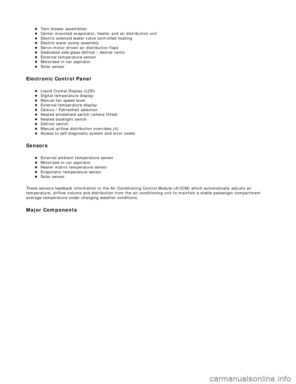
Twin blower assemblies Center mounted evaporator, heater and air distribution unit Electric solenoid water valve controlled heating Electric water pump assembly Servo motor driven air distribution flaps Dedicated side glass defrost / demist vents External temperature sensor Motorised in-car aspirator Solar sensor
Electronic Control Panel
Liquid Crystal Display (LCD) Digital temperature display Manual fan speed level External temperature display Celsius / Fahrenheit selection Heated windshield switch (where fitted) Heated backlight switch Defrost switch Manual airflow distribution overrides (4) Access to self diagnostic system and error codes
Sensors
External ambient temperature sensor Motorized in-car aspirator Heater matrix temperature sensor Evaporator temperature sensor Solar sensor
These sensors feedback information to the Air Conditioning Control Module (A/CCM) which automatically adjusts air
temperature, airflow volume and distributi on from the air conditioning unit to maintain a stable passenger compartment
average temperature under changing weather conditions.
Major Components
Page 1816 of 2490
Air Conditioning - Evaporator Core
Removal and Installation
Removal
1. Remove heater / cooler unit; refer to 82.25.21.
2. Remove air conditioning control module from heater / cooler
unit.
Slacken upper fixing.
Remove lower fixings.
3. Remove evaporator pipe firewall seal plate.
Remove screws.
Remove plate.
4. Disconnect heater matrix temperature sensor.
Detach heater matrix temperature sensor connector from
unit.
Disconnect connector.
5. Remove footwell servo motor from heater / cooler unit.
Disconnect connector.
Remove screws.
Remove motor complete with bracket.
6. Disconnect evaporator sensor connector.
Page 1827 of 2490
Maximum Cooling (temperature setting LO)
Air Conditioning Control Module (A/CCM)
Location
The A/CCM is located on the right hand side of the air conditioning unit and controls all system functions.
The temperature within the passenger compartment is continually compared with the temperature selected on the control
panel LCD. The A/CCM receives data input signals and compares these with signal s from the system temperature sensors
and feedback devices. Based on this information the A/CCM adjusts the air outlet temperatur e, airflow and distribution from
the air conditioning system in to the passenger compartment.
Identification
ItemControlOverride Allowed
Water valveFully closed (energised)-
BlowerMaximumYes
Fresh / recircRecirculationYes
Air distributionFace (state lamp OFF)Yes
A/C systemONYes
Cool air by-passFully open-
Page 1832 of 2490

RH and LH Air Intake (Fresh / Recirc) Center Vent Defrost Foot Cool Air Bypass
Blower Motor Control.
The A/CCM controls the speed of two blower motors which deliver airflow to the air conditioning unit. The blower motors are
regulated by power transistor modules which pr ovide a linear variation of blower speed.
Filter Compensation
Where particle filters are fitted as 'after market' items the A/CCM program must be changed to allow higher AUTO blower
speeds; this compensates for the slight loss of air flow. Access to the program is by PDU.
Vehicles with filters fitted OEM will have this facility enabled by Jaguars Cars Ltd.
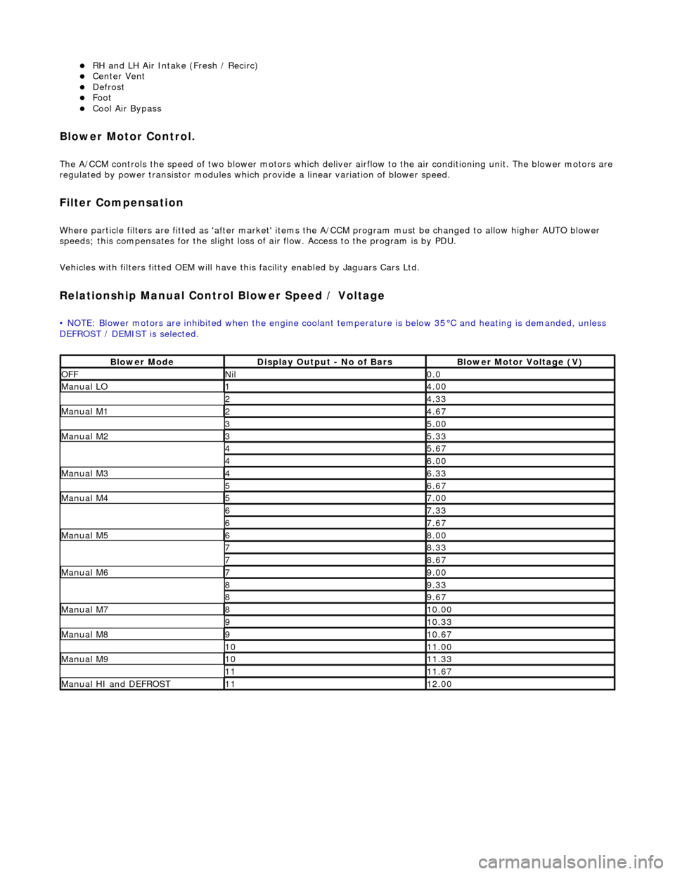
Relationship Manual Contro l Blower Speed / Voltage
• NOTE: Blower motors are inhibited when the engine coolant temperature is below 35°C and heating is demanded, unless
DEFROST / DEMIST is selected.
Blower ModeDisplay Output - No of BarsBlower Motor Voltage (V)
OFFNil0.0
Manual LO14.00
24.33
Manual M124.67
35.00
Manual M235.33
45.67
46.00
Manual M346.33
56.67
Manual M457.00
67.33
67.67
Manual M568.00
78.33
78.67
Manual M679.00
89.33
89.67
Manual M7810.00
910.33
Manual M8910.67
1011.00
Manual M91011.33
1111.67
Manual HI and DEFROST1112.00
Page 1846 of 2490
Control Components - Remote Climate Control ModuleLHD RWD
Removal and Installation
Removal
1. Position the driver's seat fully rearward
2. Glove box, 76.52.03
3. Remove the duct - passenger footwell
Remove the nut (1) duct to blower
4. Disconnect the BPM multiplug
Slacken the bolt (1), noting that it is captive in the
multiplug
Disconnect the multiplug
5. Remove the BPM
1. Remove the fixings (3), BPM to fascia reinforcement
2. Remove the BPM
6. Slacken the A/CCM upper fixing using a 'Snap-On' SDP 11
stubby screwdriver, or similar
Page 1848 of 2490
Control Components - Remote Climate Control ModuleRHD RWD
Removal and Installation
Removal
1. Position the driver's seat fully rearward
2. Position the steering column DOWN and fully EXTENDED
3. Disconnect the battery ground lead
4. Lower steering column cowl 76.46.03
5. Upper steering column cowl 76.46.02
6. Knee bolster, driver's side 76.46.11
7. Position the steering in the 'straight ahead'
8. Disconnect ALL (6) multiplugs attached to the upper column
bracket
9. WARNING: OBSERVE THE RELATED SAFETY
PROCEDURES, SEE SECTION 501-20
Disconnect the airbag multiplug
10. Detach the steering column - upper
1. Remove the bolts (2 ) upper mounting bracket
11. Detach the steering column - upper
1. Remove the pinch bolt (1) intermediate to upper column