1998 JAGUAR X308 module
[x] Cancel search: modulePage 1205 of 2490
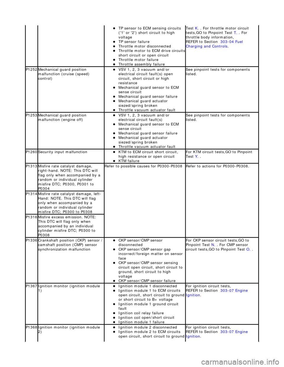
TP se
nsor to ECM sensing circuits
('1' or '2') short circuit to high
voltage
TP sensor
failure
Throttl
e motor disconnected
Th
rottle motor to ECM drive circuits
short circuit or open circuit
Throttl
e motor failure
Throttl
e assembly failure
Test
K. . F
or throttle motor circuit
tests,GO to Pinpoint Test T.
. For
throttle body i
nformation,
REFER to Section 303
-04
Fuel
Charging and Con
trols
.
P1252Mec
hanical gu
ard position
malfunction (cruise (speed)
control)
VSV 1, 2, 3 v
acuum and/or
electrical circuit fault(s) open
circuit, short circuit or high
resistance
Mechanica
l guard sensor to ECM
sense circuit
Mechanica
l guard sensor failure
Mechanica
l guard actuator
siezed/spring broken
Throttl
e vacuum actuator fault
Se
e pinpoint tests for components
listed.
P1253Mec
hanical gu
ard position
malfunction (engine off)
VSV 1, 2, 3 v
acuum and/or
electrical circuit fault(s)
Mechanica
l guard sensor to ECM
sense circuit
Mechanica
l guard sensor failure
Mechanica
l guard actuator
siezed/spring broken
Throttl
e vacuum actuator fault
Se
e pinpoint tests for components
listed.
P1260Se
curity input malfunction
K
TM to ECM circuit short circuit,
high resistance or open circuit
KTM failu
re
F
or KTM circuit tests,GO to Pinpoint
Test Y.
.
P1313M
isfire rate catalyst damage,
right-hand. NOTE: This DTC will
flag only when accompanied by a
random or individual cylinder
misfire DTC; P0300, P0301 to
P0304
R
efer to possible causes for P0300-P0308
R
efer to actions for P0300-P0308.
P1314Mi
sfire rate catalyst damage, left-
Hand: NOTE. This DTC will flag
only when accompanied by a
random or individual cylinder
misfire DTC; P0300 to P0308
P1316M
isfire excess emission. NOTE:
This DTC will flag only when
accompanied by an individual
cylinder misfire DTC; P0300 to
P0308
P1336Cranksh
aft position
(CKP) sensor /
camshaft position (CMP) sensor
synchronization malfunction
CKP s
ensor/CMP sensor
disconnected
CKP sensor/CM
P sensor gap
incorrect/foreign matter on sensor
face
CKP s
ensor/CMP sensor sensing
circuit open circuit, short circuit to
ground, short circuit to high
voltage
CKP s
ensor/CMP sensor failure
F
or CKP sensor circ
uit tests,GO to
Pinpoint Test N.
. For CM
P sensor
circuit tests,GO to Pinpoint Test O.
.
P1367Ignit
ion monitor (ignition module
1)
Ignition modu
le
1 disconnected
Ignition modul
e 1 to ECM circuits
open circuit, short circuit to ground
or short circuit to B+ voltage
Ignition modul
e 1 ground circuit
fault
Ignition coil
relay failure
Ignition coil
open/short circuit
Ignition modul
e 1 failure
F
or ignition circuit tests,
REFER to Section 303
-07
Engine
Ignition.
P1368Ignit
ion monitor (ignition module
2)
Ignition modu
le
2 disconnected
Ignition modul
e 2 to ECM circuits
open circuit, short circuit to ground
F
or ignition circuit tests,
REFER to Section 303
-07
Engine
Ignition.
Page 1206 of 2490
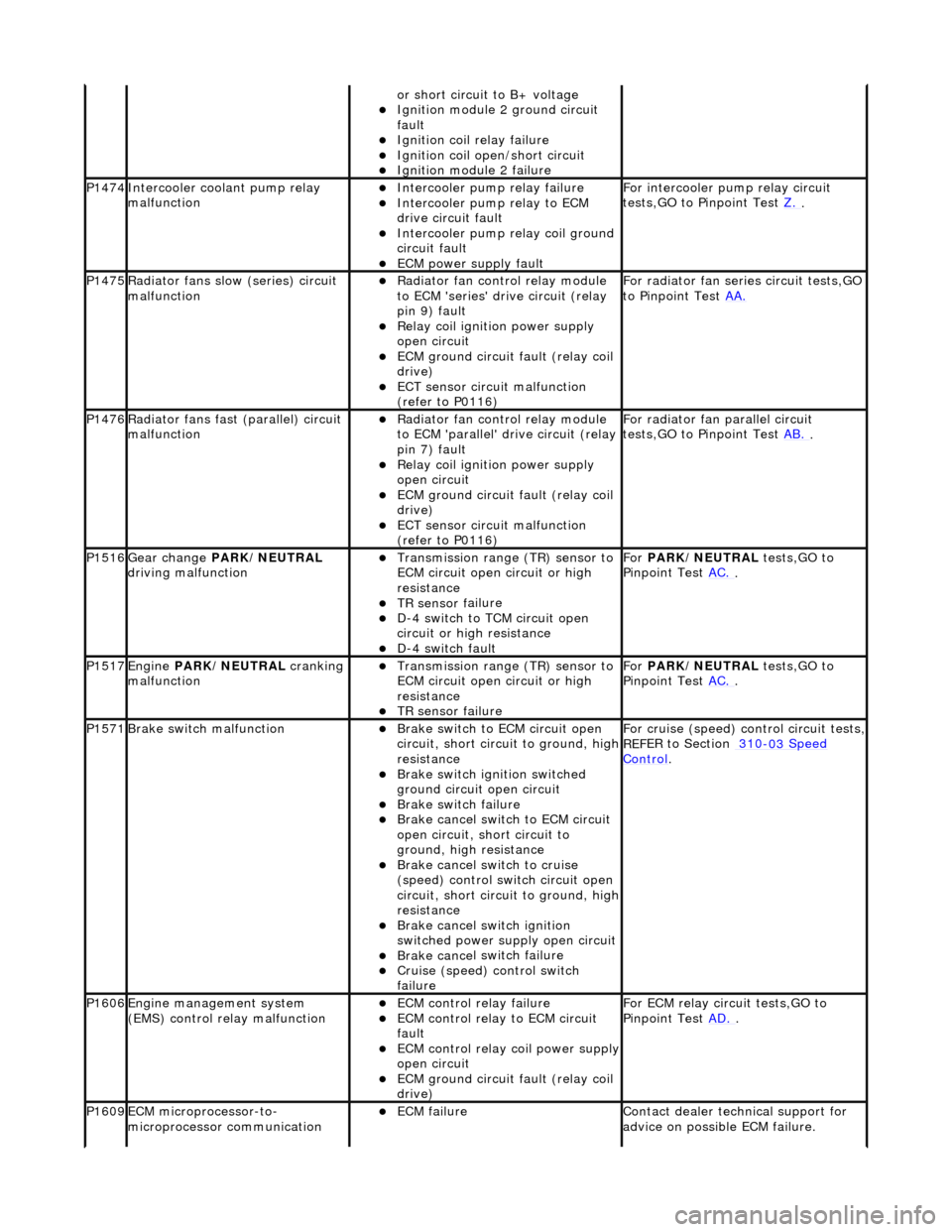
or sho
rt circuit to B+ voltage
Ignition modul
e
2 ground circuit
fault
Ignition coil relay fai
lure
Ignition coil
open/short
circuit
Ignition modul
e
2 failure
P1474Int
e
rcooler coolant pump relay
malfunction
Intercooler pump relay failure
Intercooler pump relay
to ECM
drive circuit fault
Intercooler pump relay coi
l ground
circuit fault
ECM power supply f
ault
F
or i
ntercooler pump relay circuit
tests,GO to Pinpoint Test Z.
.
P1475Ra
diator fans slow
(series) circuit
malfunction
R a
diator fan control relay module
to ECM 'series' drive circuit (relay
pin 9) fault
Relay coil ignition power supply
o p
en circuit
ECM ground circuit fault (relay coil
drive)
ECT se ns
or circuit malfunction
(refer to P0116)
F o
r radiator fan seri
es circuit tests,GO
to Pinpoint Test AA.
P1476Ra
diator fans fast (parallel) circuit
malfunction
R a
diator fan control relay module
to ECM 'parallel' drive circuit (relay
pin 7) fault
Relay coil ignition power supply
o p
en circuit
ECM ground circuit faul
t (relay coil
drive)
ECT sens
or circuit malfunction
(refer to P0116)
F or radi
ator fan parallel circuit
tests,GO to Pinpoint Test AB.
.
P1516Gear change PARK
/NEUTRAL
driving malfunction
Transmission range (T
R) sensor to
ECM circuit open circuit or high
resistance
TR sensor f
ailure
D-
4
switch to TCM circuit open
circuit or high resistance
D-4 swi
tch fault
For
PARK/NEUTRAL tests,GO to
Pinpoint Test AC.
.
P1517Engine PA
RK/NEUTRAL
cranking
malfunction
Transmissi on range (T
R) sensor to
ECM circuit open circuit or high
resistance
TR sensor f
ailure
Fo
r
PARK/NEUTRAL tests,GO to
Pinpoint Test AC.
.
P1571Brake swit
ch malfunction
Brake sw
it
ch to ECM circuit open
circuit, short circ uit to ground, high
resistance
Brake sw it
ch ignition switched
ground circuit open circuit
Brake sw it
ch failure
Brake ca
ncel
switch to ECM circuit
open circuit, short circuit to
ground, high resistance
Brake ca nce
l switch to cruise
(speed) control switch circuit open
circuit, short circ uit to ground, high
resistance
Brake cance
l switch ignition
switched power supply open circuit
Brake ca nce
l switch failure
Cru
i
se (speed) control switch
failure
For cru i
se (speed) control circuit tests,
REF
E
R to Section 310
-03
Sp
eed
Control.
P1606Engine
m
anagement system
(EMS) control relay malfunction
ECM co ntrol rel
ay failure
ECM c
o
ntrol relay to ECM circuit
fault
ECM co ntrol rel
ay coil power supply
open circuit
ECM ground circuit faul t (relay coil
drive)
F or ECM
relay circuit tests,GO to
Pinpoint Test AD.
.
P1609EC
M microprocessor-to-
microprocessor communication
ECM failu r
e
Contact deal
er techni
cal support for
advice on possible ECM failure.
Page 1207 of 2490
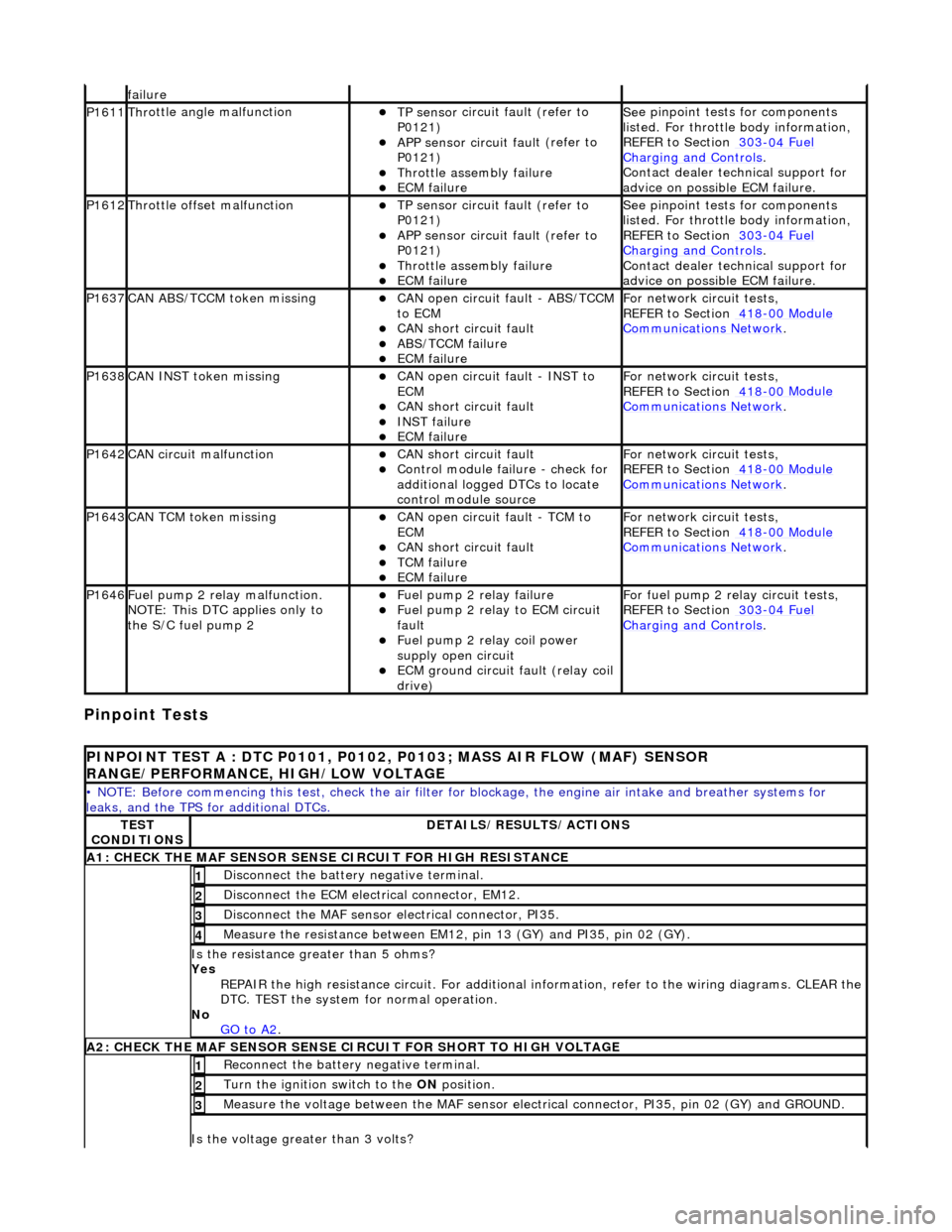
Pinpoint Tests
f
ailure
P1611Thr
ottle angle malfunction
TP sensor
circuit fault (refer to
P0121)
APP sensor circuit faul
t (refer to
P0121)
Throttl
e assembly failure
ECM failu
re
Se
e pinpoint tests for components
listed. For throttle body information,
REFER to Section 303
-04
Fuel
Charging and Con
trols
.
Contact deal
er technical support for
advice on possible ECM failure.
P1612Throttl
e offset malfunction
TP sensor
circuit fault (refer to
P0121)
APP sensor circuit faul
t (refer to
P0121)
Throttl
e assembly failure
ECM failu
re
Se
e pinpoint tests for components
listed. For throttle body information,
REFER to Section 303
-04
Fuel
Charging and Con
trols
.
Contact deal
er technical support for
advice on possible ECM failure.
P1637CAN AB
S/TCCM token missing
CAN
open circuit fault - ABS/TCCM
to ECM
CAN s
hort circuit fault
ABS/TCCM failu
re
ECM failu
re
F
or network circuit tests,
REFER to Section 418
-00
Module
Comm
unications Network
.
P1638CAN INST token missingCAN
open circuit fault - INST to
ECM
CAN s
hort circuit fault
INST
failure
ECM failu
re
F
or network circuit tests,
REFER to Section 418
-00
Module
Comm
unications Network
.
P1642CAN c
ircuit malfunction
CAN s
hort circuit fault
Control modul
e failure - check for
additional logged DTCs to locate
control module source
F
or network circuit tests,
REFER to Section 418
-00
Module
Comm
unications Network
.
P1643CAN TC
M token missing
CAN
open circuit fault - TCM to
ECM
CAN s
hort circuit fault
TCM failure
ECM failu
re
F
or network circuit tests,
REFER to Section 418
-00
Module
Comm
unications Network
.
P1646F
uel pump 2 relay malfunction.
NOTE: This DTC applies only to
the S/C fuel pump 2
F
uel pump 2 relay failure
F
uel pump 2 relay to ECM circuit
fault
F
uel pump 2 relay coil power
supply open circuit
ECM ground circuit faul
t (relay coil
drive)
F
or fuel pump 2 relay circuit tests,
REFER to Section 303
-04
Fuel
Charging and Con
trols
.
P
INPOINT TEST A : DTC P0101, P0102, P0103; MASS AIR FLOW (MAF) SENSOR
RANGE/PERFORMANCE, HIGH/LOW VOLTAGE
•
NOTE: Before commencing this
test, check the air filter for blockage, the engine air inta ke and breather systems for
leaks, and the TPS for additional DTCs.
TE
ST
CONDITIONS
D
ETAILS/RESULTS/ACTIONS
A1: CHECK
THE MAF SENSOR SENS
E CIRCUIT FOR HIGH RESISTANCE
Di
sconnect the battery negative terminal.
1
D
isconnect the ECM electrical connector, EM12.
2
Di
sconnect the MAF sensor electrical connector, PI35.
3
Meas
ure the resistance between EM12, pin 13 (GY) and PI35, pin 02 (GY).
4
Is th
e resistance greater than 5 ohms?
Yes REPAIR the high resistance circuit. For additional information, refer to the wiring diagrams. CLEAR the
DTC. TEST the system for normal operation.
No GO to A2
.
A2: CHECK
THE MAF SENSOR SENSE CI
RCUIT FOR SHORT TO HIGH VOLTAGE
R
econnect the battery negative terminal.
1
Turn the ignition swi
tch to the ON
position.
2
M
easure the voltage between the MAF sensor electrical connector, PI35, pin 02 (GY) and GROUND.
3
Is th
e voltage greater than 3 volts?
Page 1230 of 2490
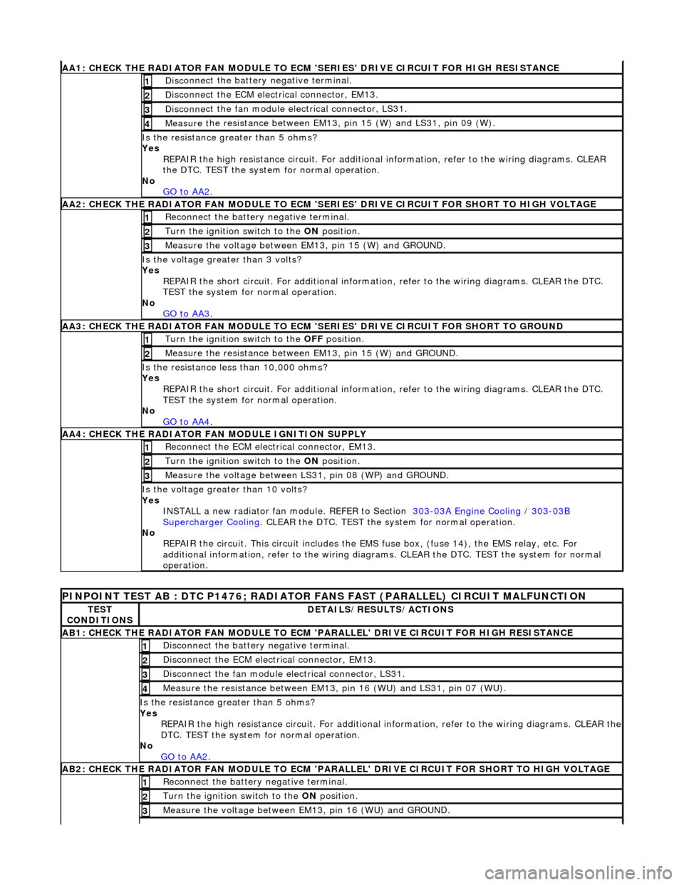
AA1: CHECK THE RA
DIATOR FAN MODULE TO ECM
'SERIES' DRIVE CIRCUIT FOR HIGH RESISTANCE
Disc
onnect the battery negative terminal.
1
D
i
sconnect the ECM electrical connector, EM13.
2
Disc
onne
ct the fan module electrical connector, LS31.
3
Meas
ure t
he resistance between EM13, pin 15 (W) and LS31, pin 09 (W).
4
Is th
e res
istance greater than 5 ohms?
Yes REPAIR the high resistance circui t. For additional information, refer to the wiring diagrams. CLEAR
the DTC. TEST the system for normal operation.
No GO to AA2
.
AA2: CHECK THE RA
DIATOR FAN MODULE TO ECM 'SER
IES' DRIVE CIRCUIT FOR SHORT TO HIGH VOLTAGE
Re
connect the battery negative terminal.
1
Turn the ignition swit
ch to the
ON position.
2
Measure t
he voltage between EM13, pin 15 (W) and GROUND.
3
Is the volt
age greater than 3 volts?
Yes REPAIR the short circuit. For addi tional information, refer to the wiring diagrams. CLEAR the DTC.
TEST the system for normal operation.
No GO to AA3
.
AA3: CHECK THE R A
DIATOR FAN MODULE TO ECM
'SERIES' DRIVE CIRCUIT FOR SHORT TO GROUND
Turn the ignition swit
ch to the
OFF position.
1
Meas ure t
he resistance between EM13, pin 15 (W) and GROUND.
2
Is
t
he resistance less than 10,000 ohms?
Yes
REPAIR the short circuit. For addi tional information, refer to the wiring diagrams. CLEAR the DTC.
TEST the system for normal operation.
No GO to AA4
.
AA4:
CHECK THE RADIATOR FAN MODULE IGNITION SUPPLY
Reconn
ect the ECM electrical connector, EM13.
1
Turn the ignition swit
ch to the
ON position.
2
Measure the voltage between LS 31,
pin 08 (WP) and GROUND.
3
Is the vol
t
age greater than 10 volts?
Yes INSTALL a new radiator fan module. REFER to Section 303
-03
A Engine Cooling
/
303-03B Supercharger Cooli
ng
. CLEA
R the DTC. TEST the sy stem f
or normal operation.
No REPAIR the circuit. This circui t includes the EMS fuse box, (f use 14), the EMS relay, etc. For
additional information, refer to the wiring diagrams. CLEAR the DT C. TEST the system for normal
operation.
PINPOINT TE ST
AB : DTC P1476; RADIATOR
FANS FAST (PARALLEL) CIRCUIT MALFUNCTION
TES
T
CONDITIONS
D E
TAILS/RESULTS/ACTIONS
AB1
:
CHECK THE RADIATOR FAN MODULE TO ECM
'PARALLEL' DRIVE CIRCUIT FOR HIGH RESISTANCE
Disc
onnect the battery negative terminal.
1
D
i
sconnect the ECM electrical connector, EM13.
2
Disc
onne
ct the fan module electrical connector, LS31.
3
Meas
ure t
he resistance between EM13, pin 16 (WU) and LS31, pin 07 (WU).
4
Is th
e res
istance greater than 5 ohms?
Yes REPAIR the high resistance circuit. For additional information, refer to the wiring diagrams. CLEAR the
DTC. TEST the system for normal operation.
No GO to AA2
.
AB2:
CHECK THE RADIATOR FAN MODULE TO ECM 'PARALLEL' DRIVE CIRCUIT FOR SHORT TO HIGH VOLTAGE
R
e
connect the battery negative terminal.
1
Turn the ignition swi
t
ch to the ON
position.
2
Measure t
he voltage between EM13, pin 16 (WU) and GROUND.
3
Page 1231 of 2490
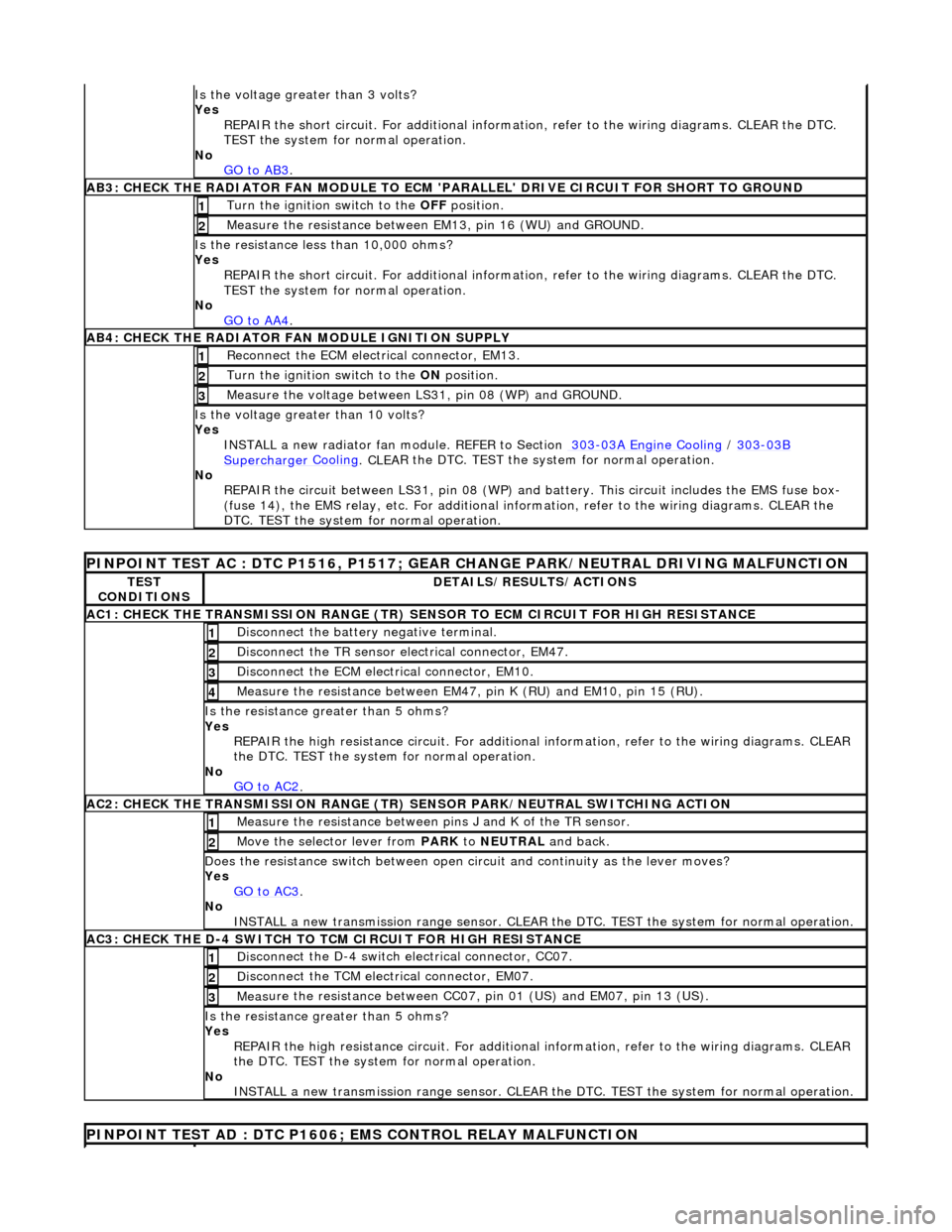
Is th
e voltage greater than 3 volts?
Yes REPAIR the short circuit. For addi tional information, refer to the wiring diagrams. CLEAR the DTC.
TEST the system for normal operation.
No GO to AB3
.
AB3
: CHECK THE RADIATOR FAN MODULE TO ECM
'PARALLEL' DRIVE CIRCUIT FOR SHORT TO GROUND
Turn the ignition swi
tch to the OFF
position.
1
Meas
ure the resistance between EM13, pin 16 (WU) and GROUND.
2
Is
the resistance less than 10,000 ohms?
Yes
REPAIR the short circuit. For addi tional information, refer to the wiring diagrams. CLEAR the DTC.
TEST the system for normal operation.
No GO to AA4
.
AB4
: CHECK THE RADIATOR FAN MODULE IGNITION SUPPLY
Re
connect the ECM electrical connector, EM13.
1
Turn the ignition swi
tch to the ON
position.
2
Measure the
voltage between LS
31, pin 08 (WP) and GROUND.
3
Is the vol
tage greater than 10 volts?
Yes INSTALL a new radiator fan module. REFER to Section 303
-0
3A Engine Cooling
/
30
3
-03
B
Supercharger
Cooling
. CLEA
R the DTC. TEST the sy
stem for normal operation.
No REPAIR the circuit between LS31, pin 08 (WP) and battery. This circuit includes the EMS fuse box-
(fuse 14), the EMS relay, etc. For additional information, refer to the wiring diagrams. CLEAR the
DTC. TEST the system for normal operation.
P
INPOINT TEST AC : DTC P1516, P1517; GEAR
CHANGE PARK/NEUTRAL DRIVING MALFUNCTION
TE
ST
CONDITIONS
D
ETAILS/RESULTS/ACTIONS
AC1: CH
ECK THE TRANSMISSION RANGE (TR) SE
NSOR TO ECM CIRCUIT FOR HIGH RESISTANCE
Di
sconnect the battery negative terminal.
1
Di
sconnect the TR sensor el
ectrical connector, EM47.
2
D
isconnect the ECM electrical connector, EM10.
3
Meas
ure the resistance between EM47, pin K (RU) and EM10, pin 15 (RU).
4
Is th
e resistance greater than 5 ohms?
Yes REPAIR the high resistance circui t. For additional information, refer to the wiring diagrams. CLEAR
the DTC. TEST the system for normal operation.
No GO to AC2
.
AC2: CH
ECK THE TRANSMISSION RANGE (TR)
SENSOR PARK/NEUTRAL SWITCHING ACTION
Meas
ure the resistance between pi
ns J and K of the TR sensor.
1
Mo
ve the selector lever from
PARK to NEUTRAL and back.
2
D
oes the resistance switch between open ci
rcuit and continuity as the lever moves?
Yes GO to AC3
.
No
INSTALL a new transmission range sensor. CLEAR th e DTC. TEST the system for normal operation.
AC3: CH
ECK THE D-4 SWITCH TO
TCM CIRCUIT FOR HIGH RESISTANCE
Di
sconnect the D-4 switch electrical connector, CC07.
1
Di
sconnect the TCM electrical connector, EM07.
2
Meas
ure the resistance between CC07,
pin 01 (US) and EM07, pin 13 (US).
3
Is th
e resistance greater than 5 ohms?
Yes REPAIR the high resistance circui t. For additional information, refer to the wiring diagrams. CLEAR
the DTC. TEST the system for normal operation.
No INSTALL a new transmission range sensor. CLEAR th e DTC. TEST the system for normal operation.
P
INPOINT TEST AD : DTC P1606;
EMS CONTROL RELAY MALFUNCTION
Page 1232 of 2490
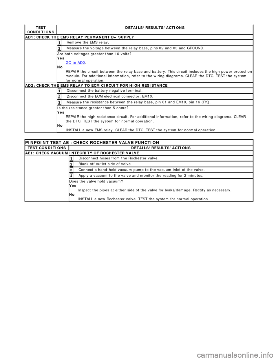
TES
T
CONDITIONS
D E
TAILS/RESULTS/ACTIONS
AD1
:
CHECK THE EMS RELAY PERMANENT B+ SUPPLY
R
e
move the EMS relay.
1
Meas
ure t
he voltage between the rela
y base, pins 02 and 03 and GROUND.
2
Are both vol
tages greater than 10 volts?
Yes GO to AD2
.
No
R
EPAIR the circuit between the rela
y base and battery. This circuit includes the high power protection
module. For additional information, refer to the wiring diagrams. CLEAR the DTC. TEST the system
for normal operation.
AD2 :
CHECK THE EMS RELAY TO ECM CIRCUIT FOR HIGH RESISTANCE
Di
sc
onnect the battery negative terminal.
1
D
i
sconnect the ECM electrical connector, EM10.
2
Meas
ure t
he resistance between the rela
y base, pin 01 and EM10, pin 16 (PK).
3
Is the res
istance greater than 5 ohms?
Yes REPAIR the high resistance circui t. For additional information, refer to the wiring diagrams. CLEAR
the DTC. TEST the system for normal operation.
No INSTALL a new EMS relay. CLEAR the DTC. TEST the system for normal operation.
PINPOINT TEST AE : CHECK
ROCHESTER VALVE FUNCTION
T
E
ST CONDITIONS
D
E
TAILS/RESULTS/ACTIONS
AE1: CHEC
K VAC
UUM INTEGRITY OF ROCHESTER VALVE
Di
sc
onnect hoses from the Rochester valve.
1
Bl
a
nk off outlet side of valve.
2
Con
n
ect a hand-held vacuum pump to the vacuum inlet of the valve.
3
Appl
y a vacuum t
o the valve and mo
nitor the reading for 2 minutes.
4
Do
es the valve hold vacuum?
Yes Inspect the pipes at either side of the valve for leaks/damage. Rectify as necessary.
No INSTALL a new Rochester valve. TEST the system for normal operation.
Page 1241 of 2490
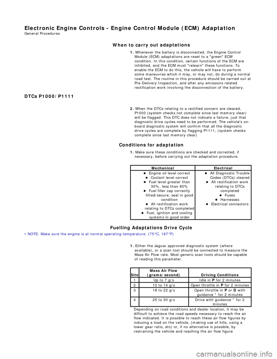
E
lectronic Engine Controls - Engine
Control Module (ECM) Adaptation
Gen
eral Procedures
When to car
ry out adaptations
DTCs P1000/P1111 Conditions for adaptation
Fuelling Adaptations Drive Cycle
•
NOTE: Make sure the engine is at normal operating
temperature. (75°C, 167°F) 1.
Whenever the battery is disconnected, the Engine Control
Module (ECM) adaptations are reset to a "green" ECM
condition. In this condition, certain functions of the ECM are
inhibited, and the ECM must "r elearn" these functions. To
enable the ECM to do this, the vehicle will have to perform
some maneuvres which it may, or may not, do during a normal
road test. The routine in this pr ocedure should be carried out at
Pre-Delivery Inspection, and after any emissions related
rectification work involving the disconnection of the battery.
2. When the DTCs relating to a rectified concern are cleared,
P1000 (system checks not complete since last memory clear)
will be flagged. This DTC does no t indicate a failure, just that
diagnostic drive cycles need to be performed. The vehicle's on-
board diagnostic system will confirm that all the diagnostic
drive cycles are complete by flagging P1111, (system checks
complete since last memory clear)
1. Make sure these conditions are checked and corrected, if
necessary, before carrying ou t the adaptation procedure.
MechanicalElectrical
Engi
ne oil level correct
Coo
lant level correct
F
uel level greater than
30%, less than 80%
F
uel filler cap correctly
fitted/secure, seal in good condition
Al
l rectification work
relating to DTCs completed
F
uel, ignition and cooling
systems in good order
Al
l Diagnostic Trouble
Codes (DTCs) cleared
Al
l rectification work
relating to DTCs completed
F
uses
Harnes
ses
E
lectrical connectors
1.
Either
the Jaguar approved diagnostic system (where
available), or a scan tool should be connected to measure the
Mass Air Flow rate. Most generi c scan tools should be capable
of reading this parameter.
Depending on road conditions and dealer location, it may be
difficult to achieve the road sp eeds necessary to reach the air
flow indicated. It is possible to reach these air flow figures by
inducing a load on the vehicle, (making use of hills, using a
lower gear ratio, etc) or, if no alternative is possible, by
restraining the vehicle and re aching the air flow figure
Si
te
Mass Air Flow
(gra
ms/second)
D
riving Conditions
1Up t
o 7 g/s
Idle
in
P for 2 minutes
21
0 to 14 g/s
O
pen throttle in
P for 2 minutes
31
8 to 22 g/s
O
pen throttle in
P or D with
guidance * for 2 minutes
42
5 to 30 g/s
D
rive with guidance * for 2
minutes
Page 1245 of 2490
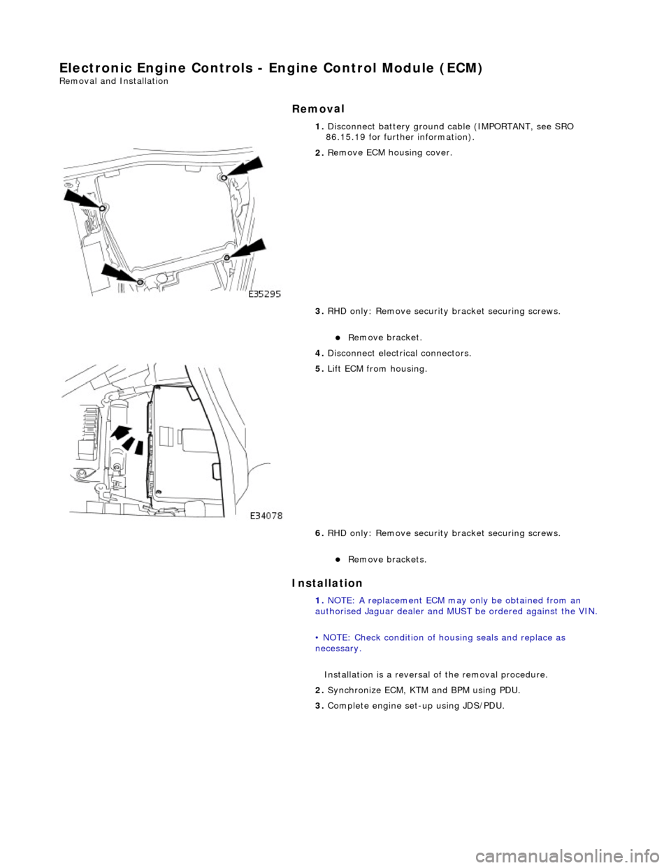
E
lectronic Engine Controls - Engine Control Module (ECM)
Re
moval and Installation
Remov
al
Installation
1.
Disc
onnect battery ground cable (IMPORTANT, see SRO
86.15.19 for further information).
2. R
emove ECM housing cover.
3. RHD only: Remove security bracket securing screws.
R
emove bracket.
4. Disconnect electrical connectors.
5. Li
ft ECM from housing.
6. RHD only: Remove security bracket securing screws.
R
emove brackets.
1. NOTE: A replacement ECM may only be obtained from an
authorised Jaguar dealer and MU ST be ordered against the VIN.
• NOTE: Check condition of ho using seals and replace as
necessary.
Installation is a reversal of the removal procedure.
2. Synchronize ECM, KTM and BPM using PDU.
3. Complete engine set- up using JDS/PDU.