Page 1492 of 2490
Automatic Transmission/Transaxle External Controls - 4.0L NA V8 -
AJ27/3.2L NA V8 - AJ26 - Se lector Lever Indicator Disc
Removal and Installation
Removal
Installation
1. Disconnect battery ground cable.
Remove the battery cover.
2. Remove the selector indicator module; 44.15.14.
3. Remove the selector indicator module disc.
Remove the disc retaining screw.
1. Installation is th e reverse of the re moval procedure.
2. Connect the battery and fit the battery cover.
Reset the radio and the clock.
Page 1495 of 2490
Automatic Transmission/Transaxle External Controls - 4.0L NA V8 -
AJ27/3.2L NA V8 - AJ26 - Selector Lever Assembly
Disassembly and Assembly
1. Disconnect battery ground cable.
Remove the battery cover.
2. Remove the shift le ver knob, 44.15.06.
3. Remove the J-gate surround, Section 501-05.
4. Remove the console finisher ve neer panel, Section 501-12.
5. Remove the center console assembly, Section 501-12.
6. Remove the indicator module, 44.15.14.
7. Detach the selector cable from the gear shift assembly.
1. Remove the inner cable to selector lever nut.
2. Slacken one outer cable locknut, keeping one positioned for reference on reassembly.
8. Remove the gear shift assembly.
Remove the four fixings.
9. Remove the slide plate.
Remove the four screws.
Page 1499 of 2490
Automatic Transmission/Transaxle External Controls - 4.0L SC V8 - AJ26 -
External Controls
Description and Operation
Introduction
Operator gearshift control is effected by:
The selector lever Accelerator pedal position Kickdown The mode switch
Operator's Selector Module ('J' Gate)
Page 1500 of 2490
ItemPart NumberDescription
1—Gear selector lever
2—Access blank - Gear-shift interlock solenoid
3—Connector - DLS
4—Dual Linear Switch (DLS)
5—Connector - Park position switch
6—Connector - Illumination module
Page 1501 of 2490

Selector lever:
Gear selector positions are:
P Transmission mechanically locked, starting available * R Reverse gear N Neutral gear, no power to the rear wheels (starting available) D Drive gear, all 5 forward gears available (see Performance Mode Pushbutton) 4 Upshift to 4th gear only 3 Upshift to 3rd gear only 2 Upshift to 2nd gear only
Gearshift Interlock Manual Override*
The interlock system which locks the sele ctor in P and prevents the ignition key from being removed except when P is
selected, may be manually overridden in the event of an emergency.
1. 1. With the parking brake applied
2. 2. Remove the access blank using a suitable Torx bit
3. 3. Insert a small screwdriver into the vacated hole
4. 4. Push the screwdriver downwards, gently, and hold whilst simultaneously moving the selector from P towards R ,
but do not engage R until the tool has been removed
5. 5. An audible warning may be heard when operation 4 is carried out
6. 6. With the selector in N and the access bl ank replaced, the vehicle may be started
Range Selection
The selector lever transmits operator demand to the transmission and TCM by means of a cable and Dual-Linear
Switch (DLS).
The lever operates the transmission assemb ly selector shaft, only for P R N D , by means of a cable. Movement of the
lever across the gate to 4, 3 and 2 positions disengages th e cable from the selector lever and engages the DLS which
controls gear selection electronically.
Gear selector module:
Provides illumination of the decal relevant to the gear sele cted. This information is provided by CAN from the TCM. Illuminates the security system Active LED on the gear selector surround, in response to an output from the BPM.
Transmission Switches
Performance Mode Pushbutton
7—Connector - Climate control
8—Solenoid - Gear selector
9—Security system Active LED
Page 1502 of 2490

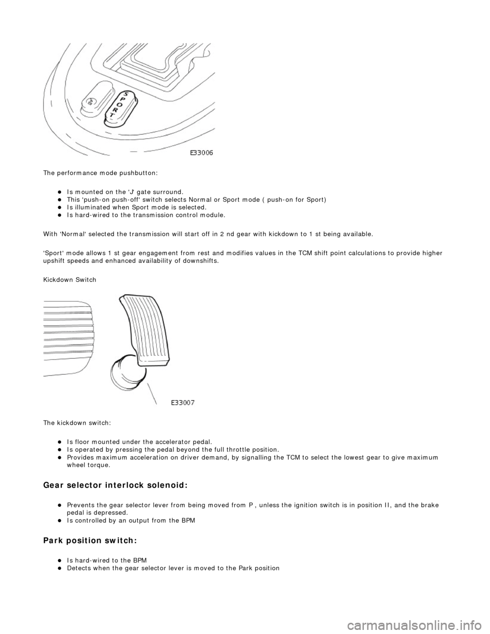
The performance mode pushbutton:
Is mounted on the 'J' gate surround. This 'push-on push-off' swit ch selects Normal or Sport mode ( push-on for Sport) Is illuminated when Sport mode is selected. Is hard-wired to the transmission control module.
With 'Normal' selected the transmissi on will start off in 2 nd gear with kickdown to 1 st being available.
'Sport' mode allows 1 st gear en gagement from rest and modifies values in the TCM shift point calculations to provide higher
upshift speeds and enhanced availability of downshifts.
Kickdown Switch
The kickdown switch:
Is floor mounted under th e accelerator pedal. Is operated by pressing the pedal beyond the full throttle position. Provides maximum acceleration on driver demand, by signalling the TCM to select the lowest gear to give maximum
wheel torque.
Gear selector interlock solenoid:
Prevents the gear selector lever from being moved from P , unless the ignition switch is in position II, and the brake
pedal is depressed.
Is controlled by an output from the BPM
Park position switch:
Is hard-wired to the BPM Detects when the gear selector lever is moved to the Park position
Page 1503 of 2490
Dual-Linear Switch (DLS)
The TCM detects gear selection by means of a switch fitted to the 'J' gate; the DLS contains two multi-track slider switches,
of which the upper controls P R N D and the lower 4 3 2 .
Output from the DLS is changed as the select or lever is moved, thus indicating selected gear position. The parallel signal is
input to the TCM by 4 discrete logic wires W0, W1, W2 and W3. The particular sequence, or gray code, will indicate which
shift position is selected, as shown in the following table where 0 = low and 1 = high:
Gray code
Transmission Unit Gear Selector
The gear selector at the transmission unit:
Is connected to the operator's selector module by cable Operates the selector valve, at the electro-hydraulic control unit
Selector PositionW3W2W1W0
P0111
R1110
N1101
D0100
41000
30010
20001
Page 1517 of 2490
Automatic Transmission/Transaxle External Contro ls - 4.0L SC V8 - AJ26 -
Selector Lever Indicator Disc
Removal and Installation
Removal
Installation
1.
Disconnect the vehicle battery ground lead.
2. Remove the selector indicator module; Operation 44.15.14.
3. Remove the selector indicator module disc.
Remove the disc retaining screw.
1. Installation is th e reverse of the re moval procedure.