Page 1885 of 2490
If the field were not controlled, the 'B+' output would rise to a level which could damage bulbs and ECMs. The regulator
compares the output voltage to an intern al voltage reference circuit to achieve the controlled output of the generator.
Suppression Module
Although the output from the generator is fi nely controlled and relatively smooth, it is still a pulsed DC output at a varying
frequency proportional to engine speed.
The suppression module damps ou t any ripple which may be sensed on the main output of the generator. This prevents
possible interference via the power supply, affecting the radio reception or, where fitted, the telephone.
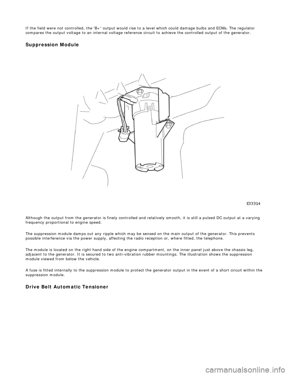
The module is located on the right hand side of the engine compartment, on the inner panel just above the chassis leg,
adjacent to the generator. It is secured to two anti-vibration rubber moun tings. The illustration shows the suppression
module viewed from below the vehicle.
A fuse is fitted internally to the suppression module to protect the generator output in the event of a short circuit within th e
suppression module.
Drive Belt Automatic Tensioner
Page 1889 of 2490
CAUTION: The engine must not be running when multiplugs are connected or disconnected.
Check that the main B+ terminal is clean and tight.
Check that the IG terminal is clean and ma king good contact; if this connection is faulty, the generator will never function
correctly.
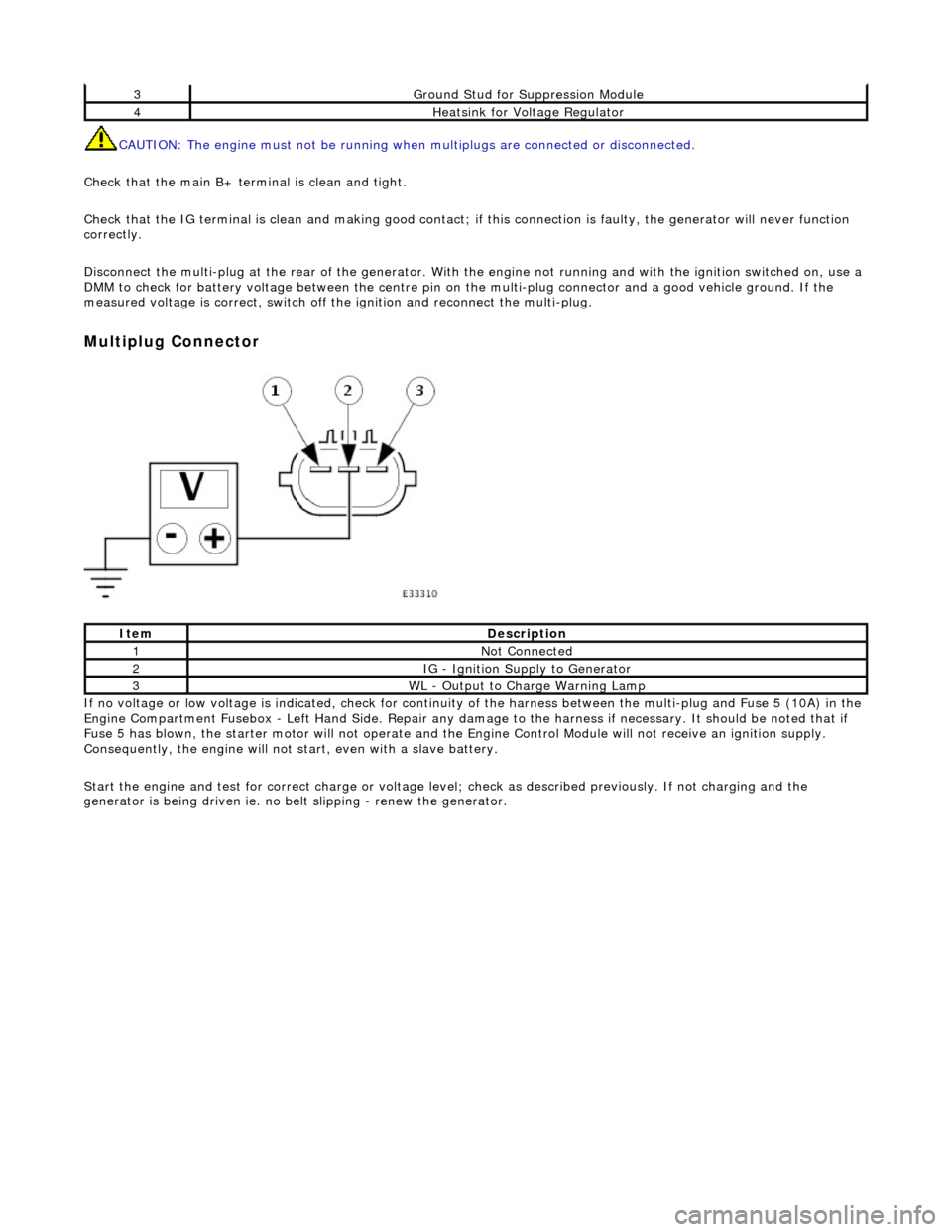
Disconnect the multi-plug at th e rear of the generator. With the engine not running and with the ignition switched on, use a
DMM to check for battery voltage between the centre pin on the multi-plug connector and a good vehicle ground. If the
measured voltage is correct, switch off the ignition and reconnect the multi-plug.
Multiplug Connector
If no voltage or low voltage is indicated, check for continuity of the harness between the multi-plug and Fuse 5 (10A) in the
Engine Compartment Fusebox - Left Hand Si de. Repair any damage to the harness if necessary. It should be noted that if
Fuse 5 has blown, the starter motor will not operate and the Engine Control Module will not receive an ignition supply.
Consequently, the engine will not st art, even with a slave battery.
Start the engine and test for correct ch arge or voltage level; check as described previously. If not charging and the
generator is being driven ie. no be lt slipping - renew the generator.
3Ground Stud for Suppression Module
4Heatsink for Voltage Regulator
ItemDescription
1Not Connected
2IG - Ignition Supply to Generator
3WL - Output to Charge Warning Lamp
Page 1891 of 2490
suppression module positive cable from the positive
terminal.
3. Where fitted, remove the nut which secures the
suppression module negati ve cable and disconnect
the cable from the generator. Reposition the
suppression module harness clear of the generator.
9. Remove the lower mounting bolt and reposition the harness
mounting bracket.
10. Remove the upper securing bolt and withdraw the generator
from the mounting bracket.
11. Carefully, manoeuvre the ge nerator forward towards the
radiator.
12. Change the position of the ge nerator and remove it upwards
between the engine and the radiator.
Page 1892 of 2490
Installation
13. Move the spacing bush rearward s slightly in the generator
mounting bracket, to ease fitting the new generator.
1. Position a suitable length bolt through the bush, fit a
tubular spacer or socket spanner, fit a nut and
tighten the assembly to move the bush slightly.
Remove the nut, bolt and spacer.
1. Fit the generator to the engine.
1. From above, position th e generator and fit the upper
mounting bolt and nut, but do not fully tighten.
2. Fit the generator lower mounting.
1. From below, reposition an d align the harness clip to
the generator lower mounting.
2. Fit the lower mounting bolt and nut, tighten to 38-48
Nm.
3. Connect the harness.
1. Reposition the suppres sion module harness and
connect the negative cable to the generator negative
terminal. Fit and tighten the terminal nut.
Page 1893 of 2490
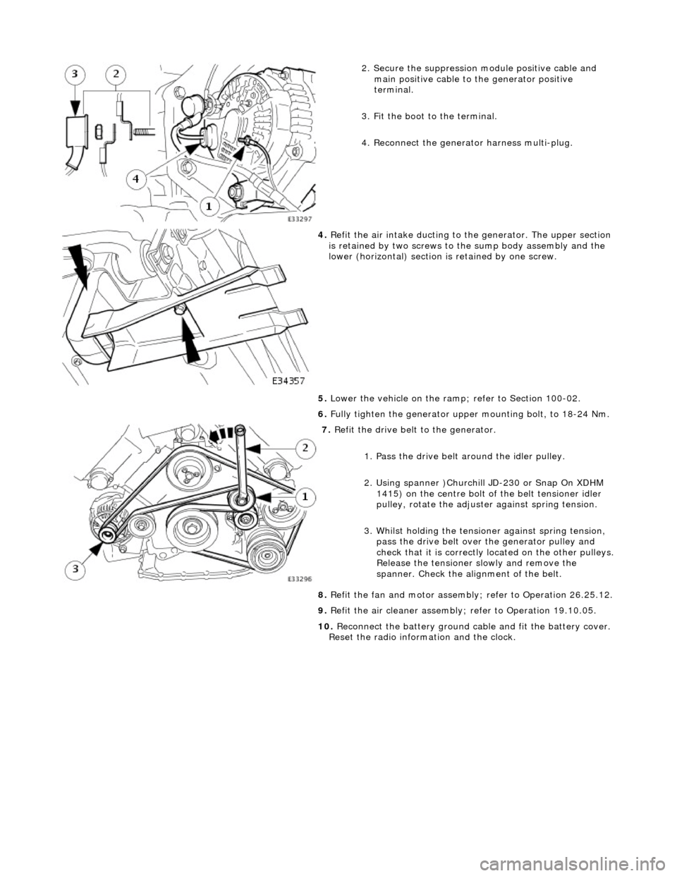
2. Secure the suppression module positive cable and
main positive cable to the generator positive
terminal.
3. Fit the boot to the terminal.
4. Reconnect the generator harness multi-plug.
4. Refit the air intake ducting to the generator. The upper section
is retained by two screws to the sump body assembly and the
lower (horizontal) section is retained by one screw.
5. Lower the vehicle on the ramp ; refer to Section 100-02.
6. Fully tighten the generator upper mounting bolt, to 18-24 Nm.
7. Refit the drive belt to the generator.
1. Pass the drive belt around the idler pulley.
2. Using spanner )Churchill JD-230 or Snap On XDHM 1415) on the centre bolt of the belt tensioner idler
pulley, rotate the adjuster against spring tension.
3. Whilst holding the tensioner against spring tension, pass the drive belt over the generator pulley and
check that it is correctly located on the other pulleys.
Release the tensioner slowly and remove the
spanner. Check the alignment of the belt.
8. Refit the fan and motor assembly ; refer to Operation 26.25.12.
9. Refit the air cleaner assembly; refer to Operation 19.10.05.
10. Reconnect the battery ground cable and fit the battery cover.
Reset the radio inform ation and the clock.
Page 1907 of 2490
Audio Unit - Capacitor
Removal and Installation
Removal
Installation
1. Disconnect the batt ery ground cable.
Remove the battery cover.
2. Raise the vehicle on a ramp.
3. Remove the suppr ession module.
1. Disconnect the multi-plug from the mounting bracket clip.
2. Disconnect the multi-plug.
3. Remove the bolts which secure the suppression module to the mounting bracket.
4. Remove the su ppression module.
1. Installation is th e reverse of the re moval procedure.
2. Reconnect the battery ground cable and fit the battery cover.
Reset the radio inform ation and the clock.
Page 1919 of 2490
Exterior Lighting - Exterior Lighting
Description and Operation
A multi-function switch located on the left stalk of the steering column switch assembly permits selection of either parking
(side), headlamps, auto-headlamp or off. Selection of a particular mode provides the appropriate input to the body
processor module (BPM).
Where the auto headlamp function is incorporated, a light sensor in the interior rear view mirror monitors ambient light and
provides an input to the BPM. The BPM responds by switching the low beam headlamps on or off as appropriate for the
prevailing light conditions.
The front and rear fog lamp switch is located on the fascia outboard of the steering column.
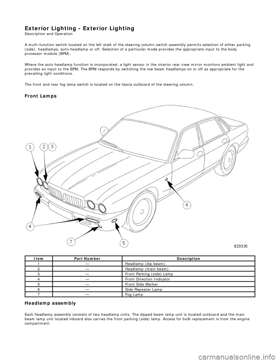
Front Lamps
Headlamp assembly
Each headlamp assembly consists of tw o headlamp units. The dipped beam lamp unit is located outboard and the main
beam lamp unit located inboard also carries the front parking (side) lamp. Access for bulb replacement is from the engine
compartment.
ItemPart NumberDescription
1—Headlamp (dip beam)
2—Headlamp (main beam)
3—Front Parking (side) Lamp
4—Front Direction Indicator
5—Front Side Marker
6—Side Repeater Lamp
7—Fog Lamp
Page 1921 of 2490
License plate lamps
Each license plate bulb is accessible after removing the relevant lens. The license plate lamps can be accessed following
removal of the trunk lid liner and upper trim finisher.
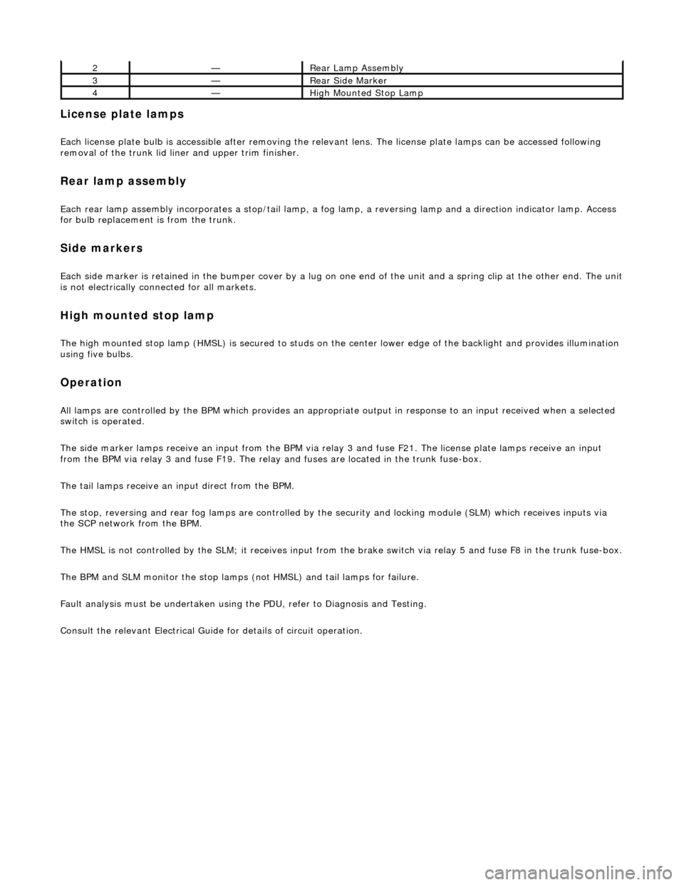
Rear lamp assembly
Each rear lamp assembly incorporates a stop/tail lamp, a fog lamp, a reversing lamp and a direction indicator lamp. Access
for bulb replacement is from the trunk.
Side markers
Each side marker is retained in the bumper cover by a lug on one end of the unit and a spring clip at the other end. The unit is not electrically connected for all markets.
High mounted stop lamp
The high mounted stop lamp (HMSL) is secu red to studs on the center lower edge of the backlight and provides illumination
using five bulbs.
Operation
All lamps are controlled by the BPM which pr ovides an appropriate output in response to an input received when a selected
switch is operated.
The side marker lamps receive an input from the BPM via relay 3 and fuse F21. The license plate lamps receive an input
from the BPM via relay 3 and fuse F19. The rela y and fuses are located in the trunk fuse-box.
The tail lamps receive an input direct from the BPM.
The stop, reversing and rear fog lamps are controlled by the security and locking module (SLM) which receives inputs via
the SCP network from the BPM.
The HMSL is not controlled by the SLM; it receives input from the brake switch via relay 5 and fuse F8 in the trunk fuse-box.
The BPM and SLM monitor the stop lamps (n ot HMSL) and tail lamps for failure.
Fault analysis must be undertaken using the PDU, refer to Diagnosis and Testing.
Consult the relevant Electrical Guid e for details of circuit operation.
2—Rear Lamp Assembly
3—Rear Side Marker
4—High Mounted Stop Lamp