Page 1260 of 2490

Automatic Transmission/Transaxle - 4.0L NA V8 - AJ27/3.2L NA V8 - AJ26
-
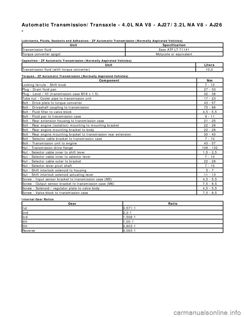
Lubri c
ants, Fluids, Sealants and Adhesives - ZF Au
tomatic Transmission (Normally Aspirated Vehicles)
Capacities - ZF Automatic Transmission (Normally Aspirated Vehicles)
Torques - ZF Automatic Transmission (Normally Aspirated Vehicles)
Internal Gear Ratios
UnitS p
ecification
Transmissi
on fluidEsso
ATF LT 71141
Torque converter spigotMolyc
o
te or equivalent
UnitLi
t
ers
Transmissi
on fluid (with
torque converter)
10
,0
Com p
onent
Nm
Locki
n
g ferrule - Shift knob
7 -
10
P
l
ug - Drain fluid pan
27
-
33
P
l
ug - Level / fill (transmission case M18 x 1.5)
32
-
38
Tu
be
nut - Cooler pipe to transmission unit
17
-
23
B
o
lt - Drive plate to torque converter
43
-
57
B
o
lt - Driveshaft coupling to transmission
75
-
88
Bo
lt
- Fluid filter to valve block
4,
5 -
5,5
Bolt
-
Fluid pan to transmission case
9 -
11
B
o
lt - Rear extension housing to transmission case
21
-
25
Bolt
-
Rear engine (isolation) mounting to mounting bracket
22
-
28
Bolt -
Rear engine moun
ting bracket to body
22
-
28
Bolt
-
Rear engine mounting bracke
t to transmission rear extension
30 -
40
B
o
lt - Selector cable bracket to transmission case
7 -
10
Bolt
-
Transmission unit to engine
43
-
57
Nu
t -
Transmission drive flange
1
08 -
132
Nu
t -
Selector cable inner to shift lever
1,
5 -
2,5
Nu
t -
Selector cable inner to selector lever
7 -
10
Nu
t -
Selector cable outer to bracket
22
-
28
Nu
t
- Selector lever pivot shaft
7 -
10
Nu
t -
Shift interlock solenoid to housing
5 -
7
Nut -
Shift interlock solenoid actuating lever
11
-
13
Sc
re
w - Input sensor bracket to transmission case (M5)
4,
5 -
5,5
Screw
-
Output sensor bracket to transmission case (M6)
7,
5 -
8,5
Screw
-
Solenoid / regulator plate to valve body
4,
5 -
5,5
Sc
re
w - Valve block to transmission case
7,
5 -
8,5
GearRatio
1s
t3,57
1:1
2n
d2,2:
1
3r
d1,50
8:1
4t
h1,00
:1
5t
h0,80
3:1
Re
ve
rse
4,
06
3:1
Page 1261 of 2490
Automatic Transmission/Transaxle - 4.0L NA V8 - AJ27/3.2L NA V8 - AJ26
- Transmission Descriptio
n
Description an
d Operation
Transmission As
sembly
Int
roduction
Compon
ent Descriptions
The t
orque converter:
Acts as a fluid
coupling between the
engine and transmission geartrain.
P
rovides multiplication of engine torque.
Cons
ists of an impeller, turbine and stat
or, housed within a converter cover.
Has a l
ock-up clutch with variable slip control.
The transmission casing:
Houses the geartrain and elec t
ro-hydraulic control unit.
Contains
the input speed sensor which measures turbine speed.
Contai
ns the output speed sensor which measures the transmission output speed.
It
em
Par
t Number
De
scription
1—Torque c
onverter housing
2—Tran
smission casing
3—Fluid pan
4—Transmission bre
ather
5—Re
ar extension housing
6—16
-way connector
7—Gear s
elector shaft
Page 1275 of 2490

Automatic Transmission/Transaxle - 4.0L NA V8 - AJ27/3.2L NA V8 - AJ26
- Diagnostic Strategy
Diagnosis and Testing
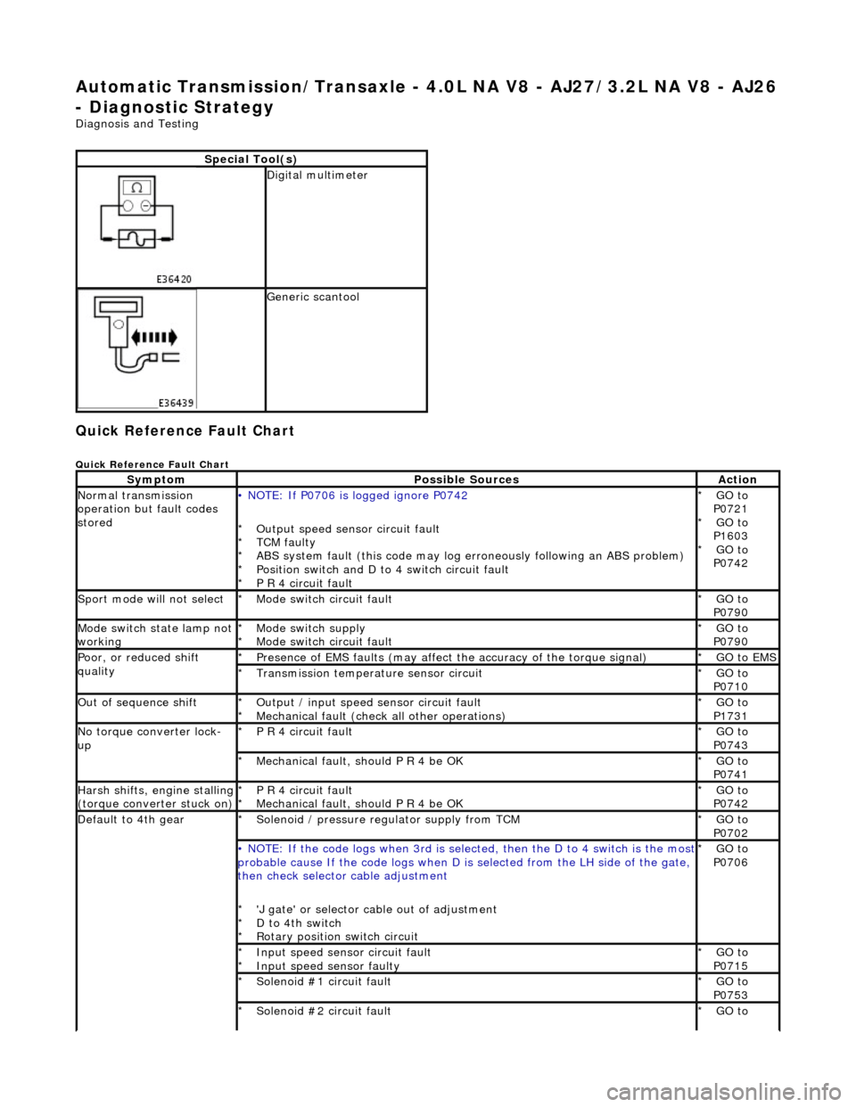
Quick Reference Fault Chart
Quick Reference Fault Chart
Special Tool(s)
Digital multimeter
Generic scantool
SymptomPossible SourcesAction
Normal transmission
operation but fault codes
stored• NOTE: If P0706 is logged ignore P0742
Output speed sensor circuit fault
TCM faulty
ABS system fault (this code may log er roneously following an ABS problem)
Position switch and D to 4 switch circuit fault
P R 4 circuit fault
*
*
*
*
*
GO to
P0721 GO to
P1603 GO to
P0742
*
*
*
Sport mode will not selectMode switch circuit fault
*GO to
P0790
*
Mode switch state lamp not
workingMode switch supply
Mode switch circuit fault
*
*GO to
P0790
*
Poor, or reduced shift
qualityPresence of EMS faults
(may affect the accuracy of the torque signal)
*GO to EMS *
Transmission temperature sensor circuit
*GO to
P0710
*
Out of sequence shiftOutput / input speed sensor circuit fault
Mechanical fault (check all other operations)
*
*GO to
P1731
*
No torque converter lock-
upP R 4 circuit fault
*GO to
P0743
*
Mechanical fault, should P R 4 be OK
*GO to
P0741
*
Harsh shifts, engine stalling (torque converter stuck on)P R 4 circuit fault
Mechanical fault, should P R 4 be OK
*
*GO to
P0742
*
Default to 4th gearSolenoid / pressure regulator supply from TCM
*GO to
P0702
*
• NOTE: If the code logs wh
en 3rd is selected, then the D to 4 switch is the most probable cause If the code logs when D is selected fro m the LH side of the gate,
then check selector cable adjustment
'J gate' or selector ca ble out of adjustment
D to 4th switch
Rotary position switch circuit
*
*
*GO to
P0706
*
Input speed sensor circuit fault
Input speed sensor faulty
*
*GO to
P0715
*
Solenoid #1 circuit fault
*GO to
P0753
*
Solenoid #2 circuit fault
*GO to
*
Page 1375 of 2490
Automatic Transmission/Transaxle - 4.0L NA V8 - AJ27/3.2L NA V8 - AJ26
- Transmission
Removal
Removal
Special Tool(s)
Engine support
303-021
Engine lifting brackets
303-536
1. Select N gear position.
2. Open the engine compartment and fit paintwork protection
sheets.
3. Disconnect battery ground cable.
Remove the battery cover.
4. Remove the engine covers (12.30.06).
5. Remove the air intake tube, MAFM and air cleaner cover assy,
(19.10.30).
6. Install engine lifting bracket 303 - 536 at the rear RH.
7. Reposition the coolant he ader tank for access.
1. Remove the securing bolt.
Page 1388 of 2490

Automatic Transmission/Transaxle - 4.0L SC V8 - AJ26 -
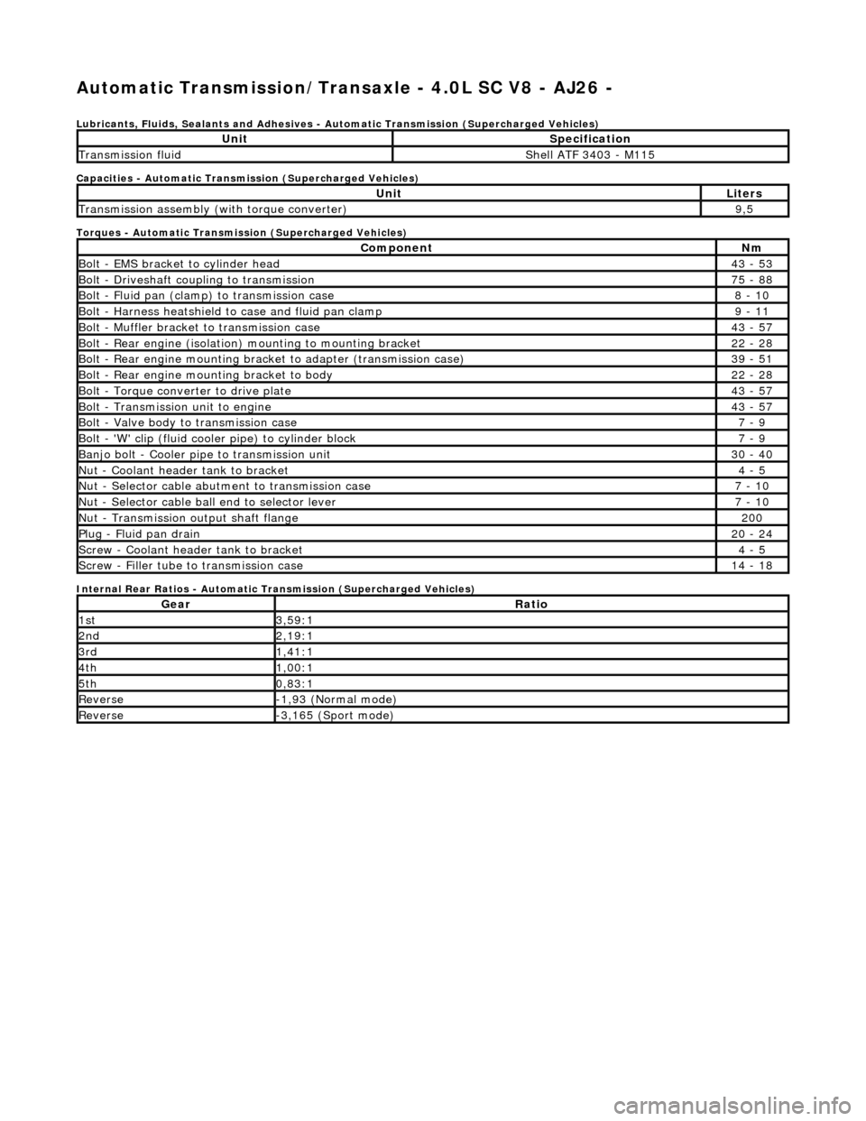
Lubricants, Fluids, Sealants and Adhesives - Automatic Transmission (Supercharged Vehicles)
Capacities - Automatic Transmission (Supercharged Vehicles)
Torques - Automatic Transmission (Supercharged Vehicles)
Internal Rear Ratios - Automatic Transmission (Supercharged Vehicles)
UnitSpecification
Transmission fluidShell ATF 3403 - M115
UnitLiters
Transmission assembly (with torque converter)9,5
ComponentNm
Bolt - EMS bracket to cylinder head43 - 53
Bolt - Driveshaft coupling to transmission75 - 88
Bolt - Fluid pan (clamp) to transmission case8 - 10
Bolt - Harness heatshield to case and fluid pan clamp9 - 11
Bolt - Muffler bracket to transmission case43 - 57
Bolt - Rear engine (isolation) mounting to mounting bracket22 - 28
Bolt - Rear engine mounting brac ket to adapter (transmission case)39 - 51
Bolt - Rear engine mounting bracket to body22 - 28
Bolt - Torque converter to drive plate43 - 57
Bolt - Transmission unit to engine43 - 57
Bolt - Valve body to transmission case7 - 9
Bolt - 'W' clip (fluid cooler pipe) to cylinder block7 - 9
Banjo bolt - Cooler pipe to transmission unit30 - 40
Nut - Coolant header tank to bracket4 - 5
Nut - Selector cable abutment to transmission case7 - 10
Nut - Selector cable ball end to selector lever7 - 10
Nut - Transmission output shaft flange200
Plug - Fluid pan drain20 - 24
Screw - Coolant header tank to bracket4 - 5
Screw - Filler tube to transmission case14 - 18
GearRatio
1st3,59:1
2nd2,19:1
3rd1,41:1
4th1,00:1
5th0,83:1
Reverse-1,93 (Normal mode)
Reverse-3,165 (Sport mode)
Page 1448 of 2490
Automatic Transmission/Transaxle - 4.0L SC V8 - AJ26 - Transmission
Removal
Removal
Special Tool(s)
Engine support
303-021
Engine lifting brackets
303-536
1. Select N gear position.
2. Disconnect the battery ground lead.
3. Remove the engine covers. Re fer to Operation 12.30.06.
4. Remove the air intake tube, MAFM and air cleaner cover
assembly. Refer to Operation 19.10.30.
5. Disconnect the transmission link lead connector.
1. Release the connector fr om its mounting bracket.
2. Disconnect the multiplug.
6. Remove the EMS harness mounting bracket.
Release the bolt, bracket to cylinder head.
7. Fit engine lifting bracket 307 - 536 at the rear RH.
Page 1464 of 2490
Automatic Transmission/Transaxle External Controls - 4.0L NA V8 -
AJ27/3.2L NA V8 - AJ26 - External Controls
Description and Operation
Introduction
Driver gearshift control is effected by:
The gear shift lever. The accelerator pedal position. The kickdown switch (where fitted). The performance mode pushbutton.
Driver's Selector Module ('J' Gate)
The gear selector lever:
Has seven positions: Park, Reverse, Neutral, Drive, Fourth, Third and Second. Operates the transmission selector shaft and rotary switch, in all positions (except Drive-to-fourth) by means of a
Bowden cable.
Passes driver gearshift requests to the transm ission control module via the rotary switch.
ItemPart NumberDescription
1—Gear selector lever
2—Drive-to-fourth switch connector
3—Neutral position switch connector
4—Park position switch connector
5—Gear selector illumination module
6—Gear selector interlock solenoid
7—Security system Active LED
Page 1478 of 2490
Automatic Transmission/Transaxle External Controls - 4.0L NA V8 -
AJ27/3.2L NA V8 - AJ26 - Brake Shift Interlock Actuator Adjustment
General Procedures
1. Disconnect battery ground cable.
Remove the battery cover.
2. Remove the J-gate surround, Section 501-05.
3. Remove the console finisher ve neer panel, Section 501-12.
4. Remove the interlock soleno id actuating lever cover.
5. Move the shift lever to N.
Operate the gearshift interlock latch manually to release
the selector lever from P .
6. NOTE: Assistance from anot her person is required.
Adjust the gearshift interlock solenoid. 1. Slacken the solenoid fixings.
2. Hold the selector lever midway between P and R .
3. Move the solenoid rearwards, against spring pressure, to take up the free play.
4. Tighten the soleno id securing nuts.
5. Ensure that the interloc k actuating lever has no free
play with the selector lever midway between P and