1998 JAGUAR X308 display
[x] Cancel search: displayPage 45 of 2490

High
tension (electrical)
ht
Hourh
Hydro
carbon
HC
I
Idl
e Air Control
IACEl
ectrical control of throttle bypass air
Idl
e Air Control Valve
IACVStepper motor dri
ven device which vari
es the volume of air by-passing the
throttle to maintain the programmed idle speed
Ignitionign
Ignition am
plifier
IAD
evice which amplifies the i
gniti
on system output
Ignition groundIGN GND
In
ertia Fuel Shut-off
IFSAn
inertia system that shuts off the fuel supply when activated by pre-
determined force limits brough t about by (e.g.) collision
In
ertia Fuel Shut-off
Switch
IFSSShut
s down fuel and ignition systems in the event of a vehicle impact
Inta
ke air
Air drawn t
hrough a cleaner and distri
buted to each cylinder for use in
combustion
InputI/PAn
electrical input signal to a controlling device
Inta
ke Air Temperature
IATTem
perature of intake air
Inta
ke Air Temperature
Sensor
IATSDe
vice used to measure IAT
Inta
ke Air Temperature
Sensor Ignition
IATSITherm
istor which signals the ECM to retard
the ignition timing in response to
high inlet air temperatures
Inta
ke Air Temperature
Sensor Injection
IATSFTher
mistor which inputs air density information to the ECM
Internal diameteri.
dia
Inte
rnational Standards
Organization
ISO
K
Kilogramme (mass)kg
Kilogram
me (force)
kg
f
Ki
logramme force per
square centimeter
kg
f/cm2
Kilom
eter
km
Ki
lometer per hour
km
/h
Kilopasc
al
kP
a
KilovoltkV
Knock
Sensor
KSSens
or which detects the onset of detonation, and signals the ECM to retard
the ignition
L
Le
ft-hand
LH
Left-hand drive veh
icle
LHD
Le
ft-hand thread
LH Thd
Ligh
t Emitting Diode
LEDLigh
t-emitting semiconductor diode used
in alphanumeric displays and as an
indicator lamp
Liqu
id Crystal Display
LCDOp
tical digital display system, applied voltage to which varies the way the
crystals reflect light, thereby modifying the display
LiterL
Low ten
sion
ltPrim
ary circuit of the ignition system, linking the battery to the primary
winding in the ignition coil
M
Malfu
nction Indicator
Lamp
MILA
required on-board indicator to aler
t the driver of an emission related
malfunction
Mani
fold Absolute
Pressure
MAPAbsolute pressure o
f the intake manifold air
Mani
fold Absolute
Pressure Sensor
MAPSSensor loca
ted in the ECM and
ported to the intake manifold
Manifol
d Surface
Temperature
MST
Mass Ai
r Flow
MAFSy
stem which provides inform
ation on the mass flow rate of the intake air to
the engine
Mass Ai
r Flow Sensor
MAFSHot-wi
re sensor which monitors air flow
into the intake manifold for fueling
and ignition control
Maxim
um
max.
Page 48 of 2490

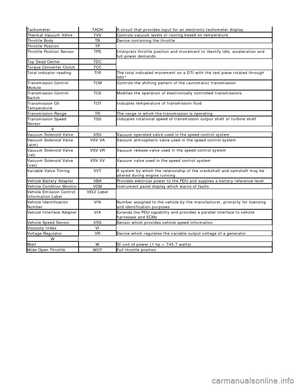
Tacho
meter
TACHA
ci
rcuit that provides input for
an electronic tachometer display
Thermal Vacuu
m Valve
TVVControls vacuum l
e
vels or
routing based on temperature
Throttle
Body
TBDe
vi
ce containing the throttle
Throttl
e
Position
TP
Throttl
e
Position Sensor
TPSInterprets throttl
e
position and movement to iden tify idle, acceleration and
full-power demands
Top Dead CenterTDC
Torque Converter C
lutch
TCC
To
tal
indicator reading
TIRThe t
o
tal indicated movement on a DTI with the test piece rotated through
360°
Transm
ission Control
Module
TCMControls
the shifting pattern
of the (automatic) transmission
Transm
ission Control
Switch
TCSModifi es
the operation of electronically controlled transmissions
Transmission Oil
TemperatureTOTIndi
cat
es temperature of transmission fluid
Transmission RangeTRThe ran
g
e in which the transmission is operating
Transmission Spe
e
d
Sensor
TSSIndi cat
es rotational speed of transmission output shaft or turbine shaft
V
Vacuu
m
Solenoid Valve
VSVVacuu
m
operated valve used in the speed control system
Vacuu
m
Solenoid Valve
(atm)
VSV VAVacuu m
atmospheric valve used in the speed control system
Vacuu
m
Solenoid Valve
(rel)
VSV VRVacuu m
release valve used in the speed control system
Vacuu
m
Solenoid Valve
(vac)
VSV VVVacuu m
valve used in the speed control system
Variable Valve TimingVVTA
s
ystem by which the relationship of the crankshaft and camshaft may be
altered during engine running
Vehi cl
e Battery Adapter
VBAProvide
s
electrical power to the PDU
and supplies a battery reference level
Vehicl
e Condition Monitor
VCMInst
rum
ent panel display which warns of faults
Ve
hic
le Emission Control
Information Label
VECI Label
Vehi cl
e Identification
Number
VINN u
mber assigned to the vehicle by the manufacturer, primarily for licensing
and identification purposes
Vehi cl
e Interface Adapter
VIAExtends the
PDU ca
pability and provid
es a parallel interface to vehicle
harnesses and ECMs
Vehicle Spe e
d Sensor
VSSSens
or which provides ve
hicle speed information
Viscosity In
dexVI
Voltage RegulatorVRDe
vice which regulates the variable output voltage of a generator
W
Wat
tWSI unit of power (1 hp = 7
45.7 watts)
W
i
de Open Throttle
WO
TFu
ll throttle position
Page 49 of 2490

Identification
Codes -
Identification Codes
Descr
iption and Operation
En
gine Number
The en
gine number (10 digits) is stamped on a raised pad on th
e front of the engine block near the thermostat housing. The
piston grade reference (8 digits) is also shown.
Automatic Transmission
Number
The
serial number of the transmission unit is displayed on
a metal or bar code label attached to the LH side of the
transmission casing.
Veh
icle Identification
Dependent
upon market, the VIN and other info
rmation is displayed on a label located ei ther on the rear edge of the LH front
door or on the body front upper crossmember. For certain mark ets, the VIN appears on a bar code label referred to as the
Certification Label and additionally carries the month and year of manufacture, vehicle weight data and paint and trim codes.
The VIN is also displayed on a plate visible through the windshie ld. It is essential that the vehicle identification number (VIN)
is quoted when ordering parts, and in all associated correspondence.
ItemDe
scription
GVW
R
G
ross Vehicle Weight Rating
GAW
R F
Gros
s Front Axle Weight Rating
GAW
R R
Gros
s Rear Axle Weight Rating
Pai
nt
Pai
nt Code
TrimTrim
Code
Page 50 of 2490

Date of
Manufacture
T
h
e date of manufacture (Build Date) of a vehicle is define
d as the calendar month and year in which the bodyshell and
powertrain are combined and the completed vehicle leaves the production line. For certain markets, VIN labels carry the
month and year of manufacture. For other markets, the vehicle Build Date is also displayed on a metal plate located at the
top of the battery tray in the trunk.
ANTI-T
HEFT LABELS
F
or
some markets, anti-theft labels bearing the VIN printed on
a special anti-forgery background are positioned on certain
body components. An additional anti-theft label is positioned on the LH side of the engine/automatic transmission casing.
Anti-theft labels must not be removed from a vehicle unless necessitated by component renewal.
ItemDe scrip
tion
1Gross Vehic
l
e Weight
2Gross Trai
n W
eight
3Maxim
u
m Permitted Front Axle Loading
4Maxim
u
m Permitted Rear Axle Loading
Page 54 of 2490

Wh en t
he vehicle is being reco
vered by rear suspended tow:
The ignition key must be remo ved from the ig
nition switch to lock the stee
ring with the front wheels facing straight
ahead.
The re ar
wheels must be
correctly positioned in the lifting cradle and securely tied down.
Em
ergency Towing
WARNING: IF THE
ENGINE IS NOT
RUNNING, THE STEERING WILL BECOME HEAVY AND THE FORCE NECESSARY TO
EFFECTIVELY APPLY THE BRAKES WILL BE GREATLY INCREASED.
• CAUTIONS:
A vehicle with a defective transmission must be towed by rear suspended tow.
The vehicle towing point is not suit able for use with a solid tow-bar.
Do not use the crossbeam tie bar as a towing location.
When the vehicle is being towed on its own wheels:
Loc a
l regulations for the towing of ve
hicles must be followed. In some co untries the registration number of the
towing vehicle and an 'On Tow' sign or warning triangle must be displayed at the rear of the towed vehicle.
The gear s
elector lever
must be in Neutral.
The
ignition switch must be in positi
on II to release the steering lock and make the direction indicators, horn and
stop lamps operate.
A di
stance of 0.8 km (0.5 mi
le) must not be exceeded.
A spe
ed of 48 km/h (30 mph) must not be exceeded.
The tow rope must be attached using th
e towi
ng location provided; refer to Front Towing Point in this section.
Rear Su
spended
Tow
Page 276 of 2490

Is hard-wi
red to the instrume
nt cluster message center.
Is hard
-wired to the J1962 diagnostic connector.
Op
era
tion
Th
e
system selects the soft or
firm damper setting according to the current ro ad and driving conditions, to optimise vehicle
ride and handling.
With the vehicle stationary, the dampers are in the firm setting, but will normally switch to the soft setting when the vehicle
exceeds 8 km/h (5 mile/h); all dampers are switched simultaneously.
Sudden movement of the vehicle body, in response to road inputs, is detected by the vertical accelerometers, and the ADCM
switches the dampers to the firm setting to give improved damping of the resultant oscillations.
When cornering forces are detected by th e lateral accelerometer, the ADCM switches the dampers to the firm setting to
reduce the roll rate an d improve wheel control.
After the event has passed, the dampers revert to the soft setting.
When the footbrake is applied, the ADCM re ceives a signal and calculates the rate of vehicle deceleration. If the deceleration
rate is greater than a certain threshold, the dampers are switched to the firm setting to reduce the pitch rate and improve
wheel control.
If a system failure occurs, the ADCM grounds the output line to the instrument cluster message center, which displays a
text warning SUSPENSION FAULT and illuminates the amber warning lamp. Under fault conditions the system always fails to
the firm setting, so that the vehicle will be safe to drive un der all road and driving conditions.
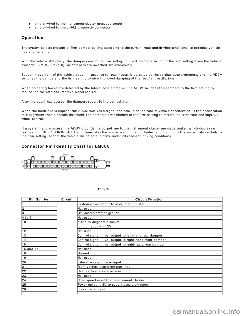
Connector Pin Identity Chart for EM068
Pin
Number
Ci
rcui
t
Circuit Functi
on
1System erro
r output to instrument
cluster
2Not
used
3O/
P a
ccelerometer ground
4 to
9
Not
used
10K-
li
ne to diagnostic socket
11Ignition su
pply +12V
12Not
used
13Control signal (+ve) output
to l
eft-hand rear damper
14Control signal (+ve) output
to right-hand front damp
er
15Control signal (+ve) output
to right-hand rear
damper
16
a
nd 17
No
t
used
18Ground
19No
t
used
20Lateral
accelerometer i
nput
21Front vertical ac
celerometer in
put
22Rear vertical
acce
lerometer input
23No
t
used
24R
o
ad speed input from
instrument cluster
25Power output +5V to suppl y accelerometers
26Brake peda
l input
Page 431 of 2490

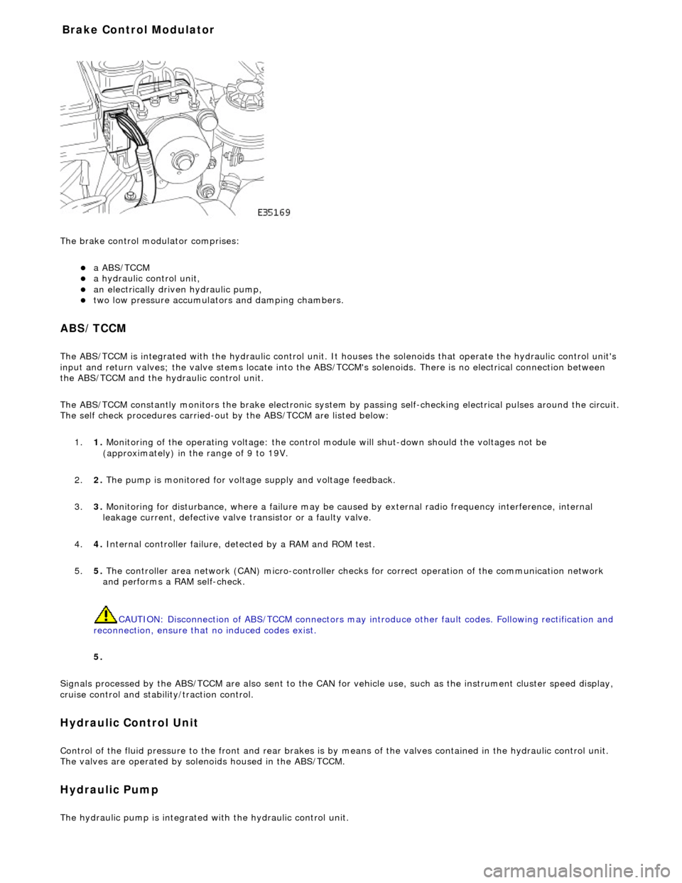
The brake
control modulator comprises:
a A
BS/TCCM
a h
ydraulic control unit,
an electrically driven hydrau
lic pump,
two low pressure accumulato
rs and damping chambers.
ABS/TCCM
The AB
S/TCCM is integrated with the hydrau
lic control unit. It houses the solenoids that operate the hydraulic control unit's
input and return valves; the valve stems locate into the ABS/TCCM's solenoids. There is no electrical connection between
the ABS/TCCM and the hydraulic control unit.
The ABS/TCCM constantly monitors the brake electronic system by passing self-checking electrical pulses around the circuit.
The self check procedures carried-out by the ABS/TCCM are listed below:
1. 1. Monitoring of the operating voltage: the control mo dule will shut-down should the voltages not be
(approximately) in the range of 9 to 19V.
2. 2. The pump is monitored for volt age supply and voltage feedback.
3. 3. Monitoring for disturbance, where a failure may be caus ed by external radio frequency interference, internal
leakage current, defective valve transistor or a faulty valve.
4. 4. Internal controller failure, de tected by a RAM and ROM test.
5. 5. The controller area network (CAN) micr o-controller checks for correct operation of the communication network
and performs a RAM self-check.
CAUTION: Disconnection of ABS/TCCM connectors may introduce other fault codes. Following rectification and
reconnection, ensure that no induced codes exist.
5.
Signals processed by the ABS/TCCM are also sent to the CAN for vehicle use, such as the instrument cluster speed display,
cruise control and stability/traction control.
Hydraulic Control Unit
Control of
the fluid pressure to
the front and rear brakes is by means of the valves contained in the hydraulic control unit.
The valves are operated by solenoids housed in the ABS/TCCM.
Hydraulic Pump
The
hydraulic pump is integrated
with the hydraulic control unit.
Bra
ke Control Modulator
Page 437 of 2490

Make sure the ignition is turned off. 1
Meas
ure the resistances between LF27,
pins 08 and 24 (B) and ground.
2
Are
the resistances less than 5 ohms?
Yes The power and ground supplies to the module are ok . Recheck the DTCs for codes indicating a fault
elsewhere.
No Repair the high resistance circui t. Refer to the electrical guides. Clear the DTC, check for normal
operation.
PINPOINT TE
ST B : CHECK THE RIGHT-HAND FRONT WSS AND CIRCUITS
•
NOTE: Check connectors and pins for damage/corrosion
(see visual inspection).
•
NOTE: Check the WSS ring condition, whee
l bearing etc. Before beginning pinpoint test s refer to the visual inspection.
TE
ST
CONDITIONS
D
ETAILS/RESULTS/ACTIONS
B1: CHECK
THE WSS OUTPUT
Disc
onnect the ABS sensor connector, FR01.
1
Connec
t a multimeter set
to read alternating curr ent volts (AC volts) between pins 1 and 2 of the
sensor.
2
Spin
the wheel by hand and check the meter display.
3
Doe
s the sensor generate a voltage?
Yes GO to B2
.
No
If the WSS ring is in good condition, install a new WSS.
REFER to: Front Wheel Speed Sensor
(20
6-09 Anti-Lock Control, Removal and Installation).
B2:
CHECK THE WSS SIGNAL CIRCUIT CONTINUITY
Make sure the ignition is off. 1
Di
sconnect the ABS module connector, LF27.
2
Meas
ure the resistance between LF27
, pin 03 (Y) and FR01, pin 02 (Y).
3
I
s the resistance less than 5 ohms?
Yes GO to B3
.
No
Repair the high resistance circui t. This circuit includes intermediate connector, LF02. Refer to the
electrical guides. Clear the DTC, check for normal operation.
B3:
CHECK THE WSS RETURN CIRCUIT CONTINUITY
Meas
ure the resistance between LF27
, pin 04 (G) and FR01, pin 01 (G).
1
I
s the resistance less than 5 ohms?
Yes The WSS and circuits are OK. Check for DTCs indicating a possible module failure.
No Repair the high resistance circui t. This circuit includes intermediate connector, LF02. Refer to the
electrical guides. Clear the DTC, check for normal operation.
P
INPOINT TEST C : CHECK THE LEFT-HAND FRONT WSS AND CIRCUITS
•
NOTE: Check connectors and pins for damage/corrosion
(see visual inspection).
•
NOTE: Check the WSS ring condition, whee
l bearing etc. Before beginning pinpoint test s refer to the visual inspection.
TE
ST
CONDITIONS
D
ETAILS/RESULTS/ACTIONS
C1
: CHECK THE WSS OUTPUT
Disc
onnect the ABS sensor connector, FL01.
1
Connec
t a multimeter set
to read alternating curr ent volts (AC volts) between pins 1 and 2 of the
sensor.
2
Spin
the wheel by hand and check the meter display.
3
Doe
s the sensor generate a voltage?
Yes GO to C2
.
No
If the WSS ring is in good condition, install a new WSS.
REFER to: Front Wheel Speed Sensor
(20
6-09 Anti-Lock Control, Removal and Installation).
C2
: CHECK THE WSS SIGNAL CIRCUIT CONTINUITY