Page 1548 of 2490
GO to B7
No Renew O2 sensor, reconnect plug(s).
GO to B8
B7: CHECK FOR O2 SENSOR FAILURE
With the conditions held as in B6, run the engine at 1500
rpm for approximately 2 minutes. 1
Does the displayed voltage drop below 400mV and rise above 500 mV, cycling approximately every 4 seconds?
Yes GO to B9
No Renew O2 sensor, reconnect plug(s).
GO to B8
B8: STOP
Perform appropriate service drive cycle and check for the
presence of DTC. 1
Has the fault code cleared?
Yes STOP
No Contact Jaguar Service
B9: HEATED O2 SENSOR SHORT CIRCUIT TO GROUND
Page 1560 of 2490
With the conditions held as in C4, run the engine at 1500
rpm for approximately 3 minutes. 1
Does the displayed voltage drop below 400mV and rise above 500
mV, cycling approximately every 180 seconds?
Yes GO to C7
No Renew O2 sensor and reconnect plug(s).
GO to C6
C6: STOP
Perform appropriate service drive cycle and check for the
presence of DTC. 1
Has the fault code cleared?
Yes STOP
No Contact Jaguar Service
C7: CHECK FOR O2 SENSOR CONTINUITY
Page 1573 of 2490
With the conditions held as in D5, run the engine at 1500
rpm for approximately 3 minutes. 1
Does the displayed voltage drop below 400mV and rise above 500
mV, cycling approximately every 180 seconds?
Yes GO to D8
No Renew O2 sensor. Reconnect plug(s).
GO to D7
D7: STOP
Perform appropriate service drive cycle and check for the
presence of DTC. 1
Has the fault code cleared?
Yes STOP
No Contact Jaguar Service
D8: CHECK FOR O2 SENSOR CONTINUITY
Page 1600 of 2490
Yes GO to F7
No Renew O2 sensor. Reconnect plug(s)
GO to F8
F7: CHECK FOR O2 SENSOR FAILURE
With the conditions held as in F6, run the engine at 1500
rpm for approximately 2 minutes. 1
Does the displayed voltage drop below 400mV and rise above
500 mV, cycling approximately every 4 seconds?
Yes GO to F9
No Renew O2 sensor. Reconnect plug(s)
GO to F8
F8: STOP
Perform appropriate service drive cycle and check for the
presence of DTC. 1
Has the fault code cleared?
Yes STOP
No Contact Jaguar Service
F9: HEATED O2 SENSOR SHORT CIRCUIT TO GROUND
Page 1613 of 2490
With the conditions held as in G4, run the engine at 1500
rpm for approximately 3 minutes. 1
Does the displayed voltage drop below 400mV and rise above 500
mV, cycling approximately every 180 seconds?
Yes GO to G7
No Renew O2 sensor and reconnect plug(s).
GO to G6
G6: STOP
Perform appropriate service drive cycle and check for the
presence of DTC. 1
Has the fault code cleared?
Yes STOP
No Contact Jaguar Service
G7: CHECK FOR O2 SENSOR CONTINUITY
Page 1626 of 2490
With
the conditions held as H3, suddenly decelerate to idle.
1
Has the voltage
d
ropped to 400mV or less ?
Yes Stop the engine
GO to H5
No Renew O2 sensor. Reconnect plug(s).
GO to H7
H5
: CHECK FOR O2 SENSOR FAILURE
Wi
th
the conditions held as H4, suddenly accelerate to
approximately 2500 rpm.
1
Has the
voltage risen to between 600mV and 1 volt?
Yes GO to H6
No Renew O2 sensor. Reconnect plug(s).
GO to H7
H6
: CHECK FOR O2 SENSOR FAILURE
W
i
th the conditions held as in H5, run the engine at 1500
rpm for approximately 3 minutes.
1
Does th e displayed voltage drop below 40
0mV and rise above 500
mV, cycling approximately every 180 seconds?
Yes
Page 1743 of 2490

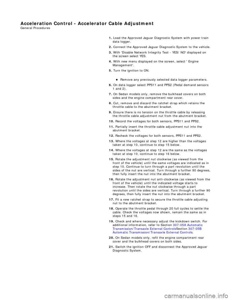
Accelerati
on Control - Accelerator Cable Adjustment
Gen
eral Procedures
1.
Load the Approved Jaguar Diagno stic System with power train
data logger.
2. Connect the Approved Jaguar Diag nostic System to the vehicle.
3. W
ith 'Disable Network Integrity Test - YES/ NO' displayed on
the screen select YES.
4. With new menu displayed on the screen, select ' Engine
Management'.
5. Turn the ignition to ON.
R
emove any previously selected data logger parameters.
6. On data logger select PPS11 an d PPS2 (Pedal demand sensors
1 and 2).
7. On Sedan models only, remove the bulkhead covers on both
sides and the engine compartment rear cover.
8. Cut, remove and discard the ra tchet strap which retains the
throttle cable to the abutment bracket.
9. Ensure there is no tension on the throttle cable by releasing
the throttle cable adjustment nut from the abutment bracket.
10. Record the voltages for both sensors, PPS11 and PPS2.
11. Partially insert the throttle cable adjustment nut into the
abutment bracket.
12. Recheck the voltages for both sensors, PPS11 and PPS2.
13. Where the voltages at step 12 are higher than the voltages
taken at step 10, contin ue to step 15 below.
14. Where the voltages at step 12 are the same as the voltages
taken at step 10, contin ue to step 16 below.
15. Rotate the adjustment nut clockwise (as viewed from the
front of the vehicle) until the same voltages are indicated as in
step 10. Continue to turn thro ugh a part revolution until the
sides of the nut are vertical. Tu rn through a further 90 degrees,
then fully insert the nut into the abutment bracket.
16. Rotate the adjustment nut anti-clockwise (as viewed from the
front of the vehicle) until the indicated voltage starts to
increase. Then rotate the nut clockwise through a part
revolution until the sides are ve rtical. Turn through a further 90
degrees, then fully insert the nut into the abutment bracket.
17. Fit a new ratchet strap to secure the throttle cable adjusting
nut to the abutment bracket.
18. Operate the throttle pedal through 20 full cycles to settle the
cable. Check the voltages now shown, remain the same as in
steps 15 and 16.
19. Check and where necessary adjust the kickdown switch. For
additional information, refer to Section 307
-05A Automatic Transmissi
on/Transaxle External Controls
Sectio
n
307
-05
B
Au
tomatic Transmission/Tra
nsaxle External Controls
.
20
.
On Sedan models only, refit the engine compartment rear
cover and the bulkhead co vers on both sides.
21. Switch the ignition OFF and disconnect the Approved Jaguar
Diagnostic System.
Page 1744 of 2490

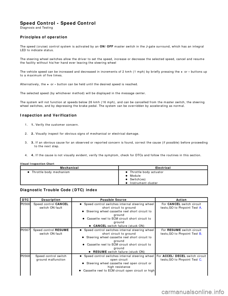
Speed Control - Speed
Control
D
iagn
osis and Testing
Pri
n
ciples of operation
The s
p
eed (cruise) control sy
stem is activated by an ON/OFF master switch in the J-gate surround, which has an integral
LED to indicate status.
The steering wheel switches allow the driver to set the speed, increase or decrease the selected speed, cancel and resume
the facility without his/her hand ever leaving the steering wheel
The vehicle speed can be increased an d decreased in increments of 2 kmh (1 mph) by briefly pressing the + or - buttons up
to a maximum of five times.
Alternatively, the + or - button can be held until th e desired speed is reached.
The selected speed (by whichever method) w ill be displayed in the message center.
The system will not function at speeds below 26 kmh (16 mph), and can be cancelled from the master switch, the steering
wheel switches, and by depressing th e brake pedal. The system can be overridden by accelerating as normal.
In
spection and Verification
1.
1. Veri fy the customer concern.
2. 2. Vis
ually inspect for obvious signs of mechanical or electrical damage.
3. 3. If an obvious cause for an observed or reported concern is found, correct the cause (if possible) before proceeding
to the next step.
4. 4. If the cause is not visually evident, verify the symptom, check for DTCs and follow the routines in this section.
Vi
sual Inspection Chart
Diagnostic Trouble Code (D
TC) index
MechanicalElectrical
Throttle body mechan
ism
Throttle body actuator
Module Switch(es) Instrument cluster
DTC
De
scr
iption
Possib
l
e Source
Acti
o
n
P0566Speed
c
ontrol
CANCEL
switch ON fault
Speed
control switches internal steering wheel
short circuit to ground
St
eering wheel cassette reel short circuit to
ground
Cassette reel to ECM circ
uit short circuit to
ground
CANCEL
switch failure (stuck ON)
Fo
r
CANCEL switch circuit
tests,GO to Pinpoint Test A.
P0567Speed c
ontrol
RESUME
switch ON fault
Speed
control switches internal steering wheel
short circuit to ground
St
eering wheel cassette reel short circuit to
ground
Cassette reel to ECM circ
uit short circuit to
ground
RESUME swit
ch failure (stuck ON)
For
RESUME switch circuit
tests,GO to Pinpoint Test B.
P0568Spee
d control switch
ground malfunction
Speed
control switches internal steering wheel
open circuit
St
eering wheel cassette reel open circuit or
high resistance
Cassette reel to ECM ci
rcuit open circuit or high
For
ACCEL/DECEL switch circuit
tests,GO to Pinpoint Test C.