1998 JAGUAR X308 unlock
[x] Cancel search: unlockPage 53 of 2490

Jacking and Lifting - Vehicle Recovery
Description an
d Operation
• NOTE: Prior to recovery, ensure that the vehicle keys are available and the security system disarmed.
Vehicle recovery methods are:
By fl
at-bed transporter.
By rear suspended tow.
By emergency to
wing for
very short distances.
Gears
hift Interlock
The
gear selector lever can only be moved
from the Park position by turning the igni tion key to position II and depressing
the brake pedal.
To remove the key from the ignition switch, the gear select or lever must be moved to the Park position. With the key
removed, the gear selector is locked in the Park position.
The selector lever can be manually unlocked from the Park position in the event of electrical failure or when moving the
vehicle without power. Refer to the general procedure in this section.
Transporter or Trailer Recovery
When the vehicle is being recove red by transporter or trailer:
The parking brake must be
be applied and the wheels chocked.
The
gear selector lever must be in Ne
utral. Do not select Park as the park ing lock mechanism may be damaged by
the forward and backward rocking motion of the vehicle.
The ve
hicle must be securely tied down to the transporter or
trailer. There are four tie-down brackets on the vehicle
underbody. Do not use the vehicle towing points or crossbeam tie bar.
Page 1263 of 2490
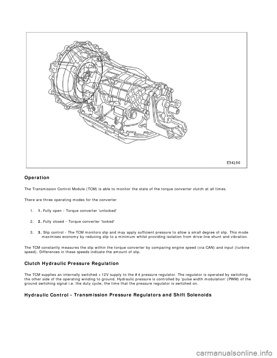
Op
eration
The T
ransmission Control Module (TCM) is
able to monitor the state of the torque converter clut ch at all times.
There are three operating modes for the converter
1. 1. Fully open - Torque converter 'unlocked'
2. 2. Fully closed - Torque converter 'locked'
3. 3. Slip control - The TCM monitors slip and may apply sufficie nt pressure to allow a small degree of slip. This mode
maximises economy by reducing slip to a minimum whilst providing isolation from drive-line shunt and vibration.
The TCM constantly measures the slip within the torque conver ter by comparing engine speed (via CAN) and input (turbine
speed). Differences in these speeds indicate the amount of slip.
Clutch Hydraulic Pressure Regulation
The T
CM supplies an internally switched +1
2V supply to the #4 pressure regulator. The regulator is operated by switching
the other side of the operating winding to ground. Hydraulic pressure is controlled by 'pulse width modulation' (PWM) of the
ground switching signal i.e. the duty cycle; the time that the pressure regulator is switched on.
Hydraulic Control
- Transmission Pre
ssure Regulators an d Shift Solenoids
Page 1693 of 2490
Filler Cap and P
ipe
The fuel
filler cap with bayonet-type fixi
ng is located beneath a remote-release sp ring-latched lid on the rear saddle panel
on the left-hand-side of the vehicle.
Fuel Pum
p
The fu
el pump(s) is energized by an ECM co
ntrolled relay. Fuel is drawn by this pu mp and supplied to the fuel injectors via
the fuel line, filter and fuel rails.
Servicing of the fuel pump re quires fuel tank removal.
Ev
aporative Loss Flange Assembly
The evaporative-loss flan
ge asse
mbly is mounted centrally on top of the tank. The flange assembly consists of a removeable
steel cap which mounts the evaporative emissions system vapor outlet valves and, if applicable, a pressure sensor. The
external electrical supply to th e fuel pump(s) is also made via a connector on the flange.
The flange assembly is fixed to the tank by a locking ring which is turned usin g special tool JD-174. A seal is fitted between
the flange assembly and the tank. Three di fferent flange assemblies are applicable according to the evaporative emission
system fitted to the vehicle. The fl ange size and fixing are identical fo r the three systems, as described.
Removal of the evaporative flange assembly is necessary to gain access to th e fuel pump(s) and other internal components.
To remove the evaporative fl ange assembly the fuel tank must first be removed.
The evaporative flange variant assemblies are described, together with service information, in Section 303-13.
Fuel R
eturn
Excess fuel
is directed back to
the fuel tank via a return line.
Fuel Pum
p Relay
The
fuel pump relay,
under control of the ECM, switches power to the fuel pump motor.
I
nertia Fuel Shutoff (IFS) Switch
The IF
S switch is located in the right-hand
side footwell behind the footboard carpet . When activated the switch isolates the
ignition system and fuel pump, releases any locked doors and disables unnecessary electrical systems. The system can be
reset by pressing down the flexible cover on the top of the switch.
• NOTE: The doors will not unlock if the IFS switch is tripped when the ignition switch is in position '0'.
Page 1981 of 2490
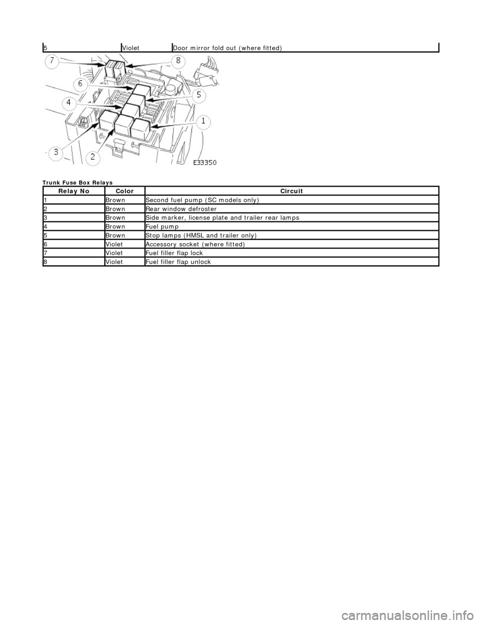
Trunk Fuse Box Relays
5VioletDoor mirror fold out (where fitted)
Relay NoColorCircuit
1BrownSecond fuel pump (SC models only)
2BrownRear window defroster
3BrownSide marker, license plate and trailer rear lamps
4BrownFuel pump
5BrownStop lamps (HMSL and trailer only)
6VioletAccessory socket (where fitted)
7VioletFuel filler flap lock
8VioletFuel filler flap unlock
Page 2009 of 2490
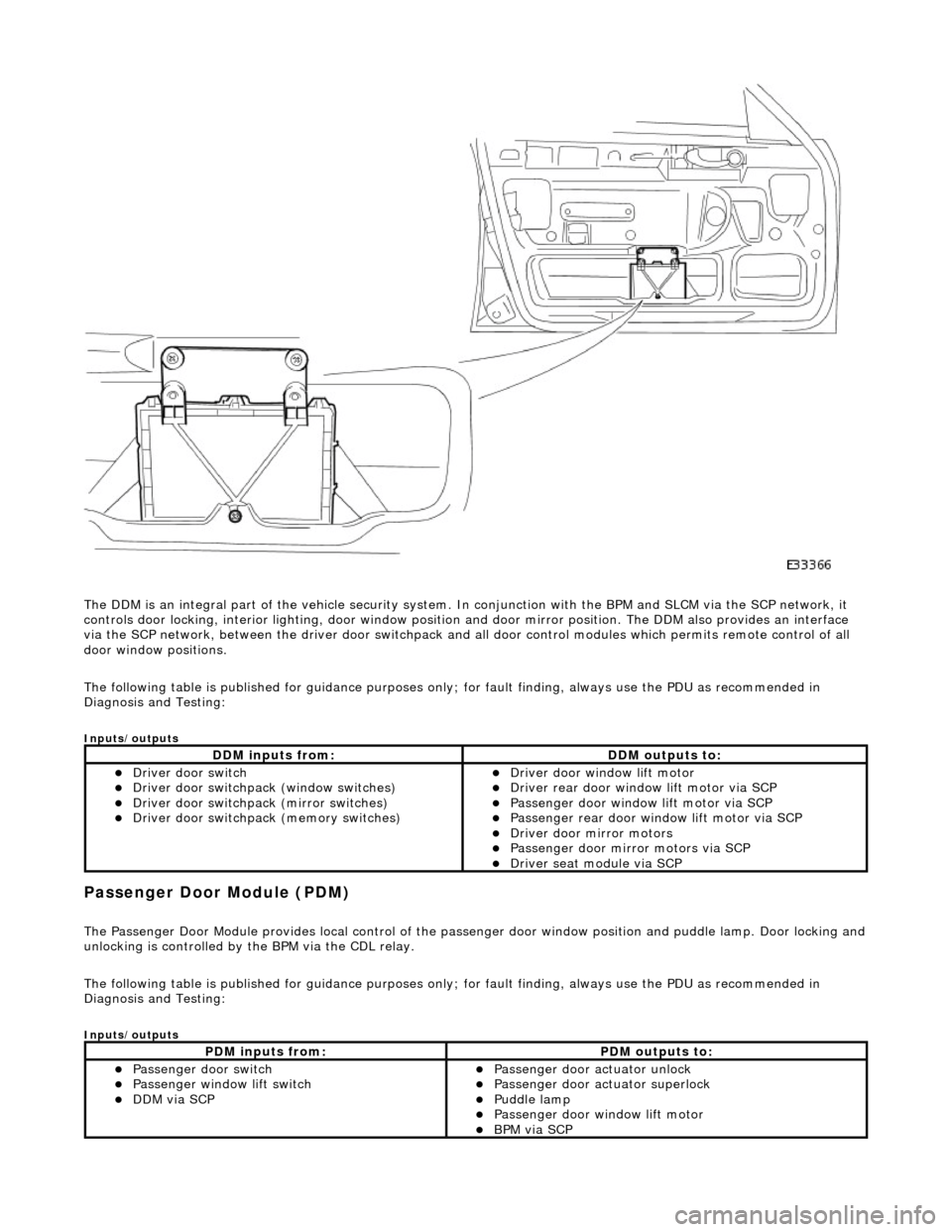
The DDM is an integral part of the vehi cle security system. In conjunction with the BPM and SLCM via the SCP network, it
controls door locking, interior lighting, door window position and door mirror position. The DDM also provides an interface
via the SCP network, between the driver door switchpack and all door control modules which permits remote control of all
door window positions.
The following table is published for guidance purp oses only; for fault finding, always use the PDU as recommended in
Diagnosis and Testing:
Inputs/outputs
Passenger Door Module (PDM)
The Passenger Door Module provides local control of the pass enger door window position and puddle lamp. Door locking and unlocking is controlled by the BPM via the CDL relay.
The following table is published for guidance purp oses only; for fault finding, always use the PDU as recommended in
Diagnosis and Testing:
Inputs/outputs
DDM inputs from:DDM outputs to:
Driver door switch Driver door switchpack (window switches) Driver door switchpack (mirror switches) Driver door switchpack (memory switches)
Driver door window lift motor Driver rear door window lift motor via SCP Passenger door window lift motor via SCP Passenger rear door window lift motor via SCP Driver door mirror motors Passenger door mirror motors via SCP Driver seat module via SCP
PDM inputs from:PDM outputs to:
Passenger door switch Passenger window lift switch DDM via SCP
Passenger door actuator unlock Passenger door actuator superlock Puddle lamp Passenger door window lift motor BPM via SCP
Page 2010 of 2490
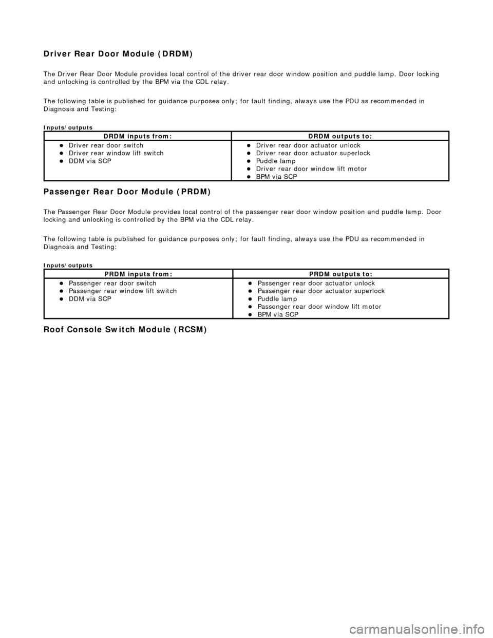
Driver Rear Door Module (DRDM)
The Driver Rear Door Module provides local control of the driver rear door window position and puddle lamp. Door locking
and unlocking is controlled by the BPM via the CDL relay.
The following table is published for guidance purp oses only; for fault finding, always use the PDU as recommended in
Diagnosis and Testing:
Inputs/outputs
Passenger Rear Door Module (PRDM)
The Passenger Rear Door Module provides local control of th e passenger rear door window position and puddle lamp. Door
locking and unlocking is controlled by the BPM via the CDL relay.
The following table is published for guidance purp oses only; for fault finding, always use the PDU as recommended in
Diagnosis and Testing:
Inputs/outputs
Roof Console Switch Module (RCSM)
DRDM inputs from:DRDM outputs to:
Driver rear door switch Driver rear window lift switch DDM via SCP
Driver rear door actuator unlock Driver rear door actuator superlock Puddle lamp Driver rear door window lift motor BPM via SCP
PRDM inputs from:PRDM outputs to:
Passenger rear door switch Passenger rear window lift switch DDM via SCP
Passenger rear door actuator unlock Passenger rear door actuator superlock Puddle lamp Passenger rear door window lift motor BPM via SCP
Page 2116 of 2490
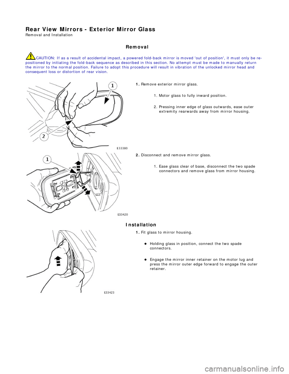
Rear View Mirrors - Exterior Mirror Glass
Removal and Installation
Removal
CAUTION: If as a result of accidental impact, a powered fold-back mirror is mo ved 'out of position', it must only be re-
positioned by initiating the fold-back sequence as described in this section. No attempt must be made to manually return
the mirror to the normal position. Failure to adopt this procedure will result in vibration of the unlocked mirror head and
consequent loss or distortion of rear vision.
Installation
1. Remove exterior mirror glass.
1. Motor glass to fully inward position.
2. Pressing inner edge of glass outwards, ease outer
extremity rearwards away from mirror housing.
2. Disconnect and remove mirror glass.
1. Ease glass clear of base, disconnect the two spade connectors and remove gl ass from mirror housing.
1. Fit glass to mirror housing.
Holding glass in position , connect the two spade
connectors.
Engage the mirror inner retainer on the motor lug and
press the mirror outer edge fo rward to engage the outer
retainer.
Page 2273 of 2490
Handles, Locks, Latches and Entry Systems - Handles, Locks, Latches and
Entry Systems
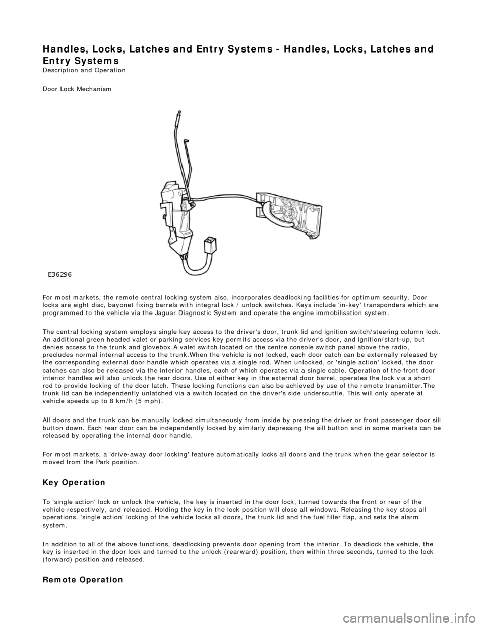
Description and Operation
Door Lock Mechanism
For most markets, the remote central locking system also, in corporates deadlocking facilities for optimum security. Door
locks are eight disc, bayonet fixing barrels with integral lock / unlock switches. Keys include 'in-key' transponders which are
programmed to the vehicle via the Jaguar Diagnostic Sy stem and operate the engine immobilisation system.
The central locking system employs single key access to the driv er's door, trunk lid and ignition switch/steering column lock.
An additional green headed valet or park ing services key permits access via the driver's door, and ignition/start-up, but
denies access to the trunk and glovebox.A valet switch located on the centre console switch panel above the radio,
precludes normal internal access to the trunk.When the vehicle is not locked, each door catch can be externally released by
the corresponding external door handle which operates via a si ngle rod. When unlocked, or 'single action' locked, the door
catches can also be released via the interior handles, each of which operates via a single cable. Operation of the front door
interior handles will also unlock the rear doors. Use of either key in the external door barrel, operates the lock via a short
rod to provide locking of the door latch. These locking functions can also be achieved by use of the remote transmitter.The
trunk lid can be independently unlatched via a switch located on the driver's side underscuttle. This will only operate at
vehicle speeds up to 8 km/h (5 mph).
All doors and the trunk can be manually lock ed simultaneously from inside by pressing the driver or front passenger door sill
button down. Each rear door can be independently locked by si milarly depressing the sill button and in some markets can be released by operating the internal door handle.
For most markets, a 'drive-away door locking' feature automati cally locks all doors and the trunk when the gear selector is
moved from the Park position.
Key Operation
To 'single action' lock or unlock the vehicle, the key is inserted in the door lock , turned towards the front or rear of the
vehicle respectively, and released. Holding the key in the lock position will close all windows. Releasing the key stops all
operations. 'single action' locking of the vehicle locks all doors, the trunk lid and the fuel filler flap, and sets the alarm
system.
In addition to all of the above functions, deadlocking prevents door opening from th e interior. To deadlock the vehicle, the
key is inserted in the door lock and turned to the unlock (rearw ard) position, then within three seconds, turned to the lock
(forward) position and released.
Remote Operation