1998 JAGUAR X308 display
[x] Cancel search: displayPage 1162 of 2490
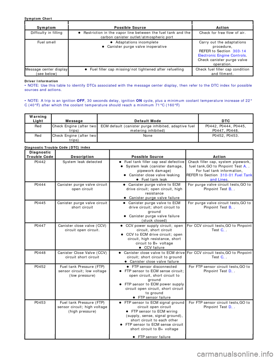
Driver Info
rmation
•
NOTE: Use this table to identify DTCs associated with the me
ssage center display, then refer to the DTC index for possible
sources and actions.
• NOTE: A trip is an ignition OFF, 30 seconds delay, ignition ON cycle, plus a minimum coolant temperature increase of 22°
C (40°F) after which the coolant temperat ure should reach a minimum 71°C (160°F)
Diagnostic Trouble C
ode (DTC) index
Sy
m
ptom
Possib
l
e Source
Acti
o
n
D
i
fficulty in filling
R
e
striction in the vapor line between the fuel tank and the
carbon canister outlet/atmospheric port
Check f or free f
low of air.
F
u
el smell
Adaptat
i
ons incomplete
Cani
st
er purge valve inoperative
Carry
o
ut the adaptations
procedure,
REFER to Section 303
-14 Ele c
tronic Engine Controls
.
Chec k cani
ster purge valve
operation.
M e
ssage center display
(see below)
Fue l
filler cap missing/not
tightened after refuelling
Check fu
el filler cap condition
and fitment.
Warning Li
ght
Mess
age Defaul
t Mode
DT
C
RedCheck Engine (after two
trip
s)
ECM de
fa
ult (canister purge inhibited, adaptive fuel
metering inhibited)
P0442,
P0444, P0445,
P0447, P0448.
Re dCheck Engine (after two
trip
s)
No
neP04 52,
P0453.
Di
agno
stic
Trouble Code
De scr
iption
Possib
l
e Source
Acti
o
n
P0442Sy
st
em leak detected
F
u
el tank filler cap seal defective
Sy
ste
m leak (c
anister damage,
pipework damage)
Cani st
er close valve leaking
F
u
el tank leak
Chec
k fi
ller cap,
system pipework,
fuel tank,GO to Pinpoint Test A.
.
F o
r fuel tank information,
REFER to Section 310
-01 Fu
el Tank
and Lines.
P0444Canist
er purge valve circuit
open circuit
Cani st
er purge valve to ECM
drive circuit; open circuit, high
resistance
Cani st
er purge valve failure
F
or purge
valve circuit tests,GO to
Pinpoint Test B.
.
P0445Canist
er purge valve circuit
short circuit
Cani st
er purge valve to ECM
drive circuit; short circuit to ground
Canist
er purge valve failure
(stuck closed)
F or purge
valve circuit tests,GO to
Pinpoint Test B.
.
P0447Canist
er close valve (CCV)
circuit open circuit.
CCV power su pply ci
rcuit; open
circuit, short circuit
CCV to ECM drive circuit;
open
circuit, high resistance, short circuit to B+ voltage
CCV failure
Fo
r CCV circuit tests,GO to Pinpoint
Test C.
.
P0448Canist
er Close Valve (CCV)
circuit short circuit
Cani st
er close valve to ECM drive
circuit; short circuit to ground
Cani st
er close valve failure
F
o
r CCV circuit tests,GO to Pinpoint
Test C.
.
P0452 Fu
el tank Pressure (FTP)
sensor circuit; low voltage (low pressure)
FTP sen
sor disconnected
FTP sen
sor to ECM sense circuit;
open circuit, short circuit to ground
FTP sens
or to ECM power supply
circuit open circuit, short circuit to ground
FT
P sensor failure
For FT
P se
nsor circuit tests,GO to
Pinpoint Test D.
.
P0453Fu
el tank Pressure (FTP)
sensor circuit; high voltage
(high pressure)
FTP sen
sor to ECM signal ground
circuit open circuit
F T
P sensor to ECM wiring
(supply, sense, signal ground),
short circuit to each other
FTP sen
sor to ECM sense circuit
short circuit to B+ voltage
For FT P se
nsor circuit tests,GO to
Pinpoint Test D.
.
FT
P sensor failure
Sym
ptom Chart
Page 1189 of 2490
E
lectronic Engine Controls -
Electronic Engine Controls
D
iagnosis and Testing
I
nspection and Verification
1.
1. Veri
fy the customer concern.
2. 2. Confirm which, if any, warning li ghts and/or messages were displayed on the instrument cluster.
• NOTE: If any warning lights and/or me ssages were displayed when the fault occurred, refer to the Driver Information
table for DTCs associated with the display, then to the DTC index table for possible sources and actions. Some warnings will
appear to clear when the ignition is cycl ed. This is often because the warning has flagged as a resu lt of one of the vehicle's
on-board diagnostic routines having run to detect the fault. If the same routine is not run when the ignition is switched ON,
the warning will not reflag until the routine does run. See the DTC summaries for drive cycle routines.
3. 3. Visually inspect for obvious signs of mechanical or electrical damage.
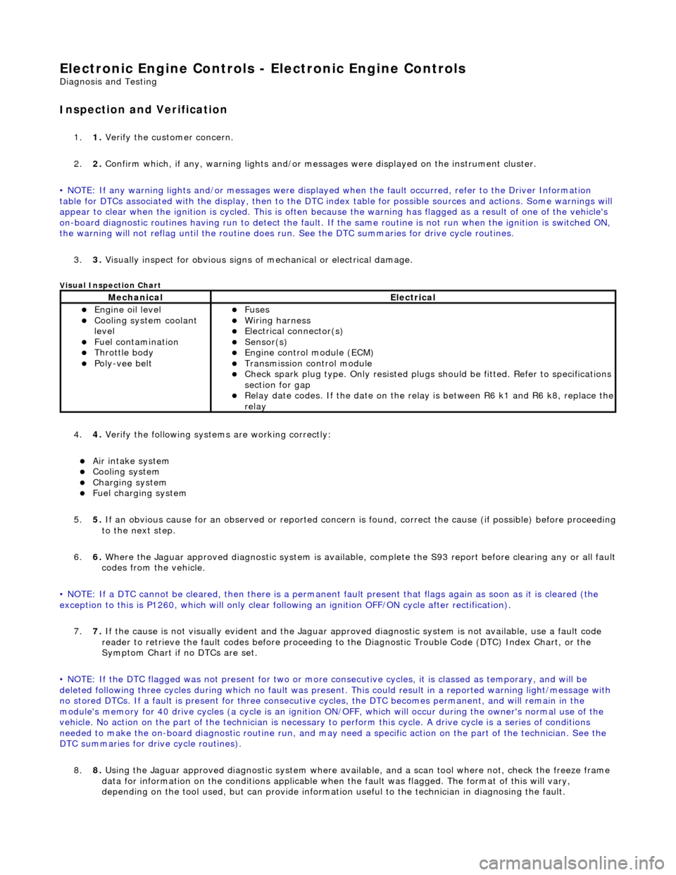
V
isual Inspection Chart
4.
4. Veri
fy the following syst
ems are working correctly:
Air in
take system
Coo
ling system
Charging system
F
uel charging system
5. 5. If an obvious cause for an observed or reported concern is found, correct the cause (if possible) before proceeding
to the next step.
6. 6. Where the Jaguar approved diagnostic sy stem is available, complete the S93 report before clearing any or all fault
codes from the vehicle.
• NOTE: If a DTC cannot be cleared, then there is a permanent fault present that flag s again as soon as it is cleared (the
exception to this is P1260, which will only clear following an ignition OFF/ON cycle after rectification).
7. 7. If the cause is not visually evident and the Jaguar approv ed diagnostic system is not available, use a fault code
reader to retrieve the fault codes be fore proceeding to the Diagnostic Trou ble Code (DTC) Index Chart, or the
Symptom Chart if no DTCs are set.
• NOTE: If the DTC flagged was not present for two or more co nsecutive cycles, it is classed as temporary, and will be
deleted following three cycl es during which no fault was present. This could result in a reported wa rning light/message with
no stored DTCs. If a fault is present for three consecutive cycles, the DTC becomes permanent, and will remain in the
module's memory for 40 drive cycles (a cy cle is an ignition ON/OFF, which will occur during the owner's normal use of the
vehicle. No action on the part of the technician is necessary to perform this cycle. A drive cycle is a series of conditions
needed to make the on-board diagnostic ro utine run, and may need a specific action on the part of the technician. See the
DTC summaries for driv e cycle routines).
8. 8. Using the Jaguar approved diagnostic system where available, and a scan tool where not, check the freeze frame
data for information on the conditions applicable when the fault was flagged. The format of this will vary,
dependin
g o
n the tool used, but can provide information useful to the technician in dia
gnos
in
g th
e fault.
MechanicalElectrical
Engi
ne oil level
Coo
ling system coolant
level
Fuel contamination
Throttle body Poly
-vee belt
F
uses
W
iring harness
E
lectrical connector(s)
Sens
or(s)
Engine
control module (ECM)
Tran
smission control module
Check spark plu
g type. Only re
sisted plugs should be fitted. Refer to specifications
section for gap
Relay date codes.
If the date on the rela
y is between R6 k1 and R6 k8, replace the
relay
Page 1192 of 2490
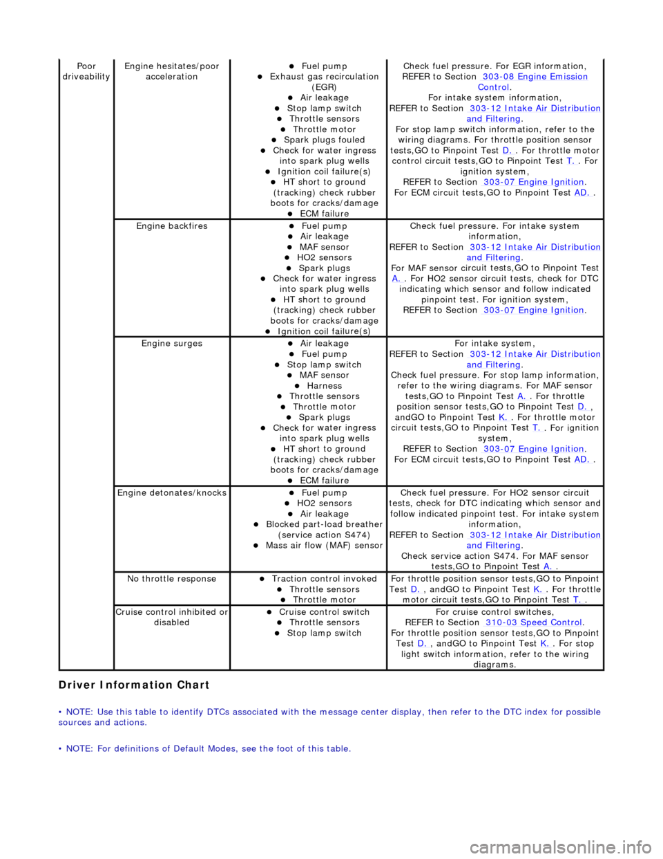
Driver Information
Chart
•
NOTE: Use this table to identify DTCs associated with the me
ssage center display, then refer to the DTC index for possible
sources and actions.
• NOTE: For definitions of Default Modes, see the foot of this table.
Poor
dr iveabilityEngine h e
sitates/poor
acceleration
Fue l
pump
Exhaus
t gas
recirculation
(EGR)
Air leakage Stop lamp swi t
ch
Throttl
e
sensors
Throttl
e
motor
Spark
plugs
fouled
Check f
o
r water ingress
into spark plug wells
Ignition coil fail
ure(s)
HT sh
o
rt to ground
(tracking) check rubber
boots for cracks/damage
ECM failu r
e
Check f
u
el pressure. For EGR information,
REFER to Section 303
-08 En gin
e Emission
Control.
F or i
ntake system information,
REFER to Section 303
-1 2
Intake Air Distribution
and F
ilt
ering
.
F or stop l
amp switch in
formation, refer to the
wiring diagrams. For throttle position sensor
tests,GO to Pinpoint Test D.
. Fo
r throttle motor
control circuit tests,GO to Pinpoint Test T.
. For
igni t
ion system,
REFER to Section 303
-07 En
gine Ignition
.
F or ECM
circuit tests,GO to Pinpoint Test
AD.
.
Engine backfiresFuel
pump
Air leakage MAF se
nsor
HO2 sensors
Spark plugs Check fo
r water ingress
into spark plug wells
HT sh o
rt to ground
(tracking) check rubber
boots for cracks/damage
Ignition coil fail
ure(s)
Chec
k fu
el pressure. For intake system
information,
REFER to Section 303
-12
Intake Air Distribution
and Filt
ering
.
F or MAF sensor ci
rcuit test
s,GO to Pinpoint Test
A.
. F or HO2 sensor
circui
t tests, check for DTC
indicating which sensor and follow indicated pinpoint test. For ignition system,
REFER to Section 303
-07 En
gine Ignition
.
Engine
s
urges
Air leakage
Fuel
pump
Stop lamp swit
ch
MAF s
e
nsor
Harness Throttl
e
sensors
Throttl
e
motor
Spark plugs
Check fo
r water ingress
into spark plug wells
HT sh o
rt to ground
(tracking) check rubber
boots for cracks/damage
ECM failu r
e
Fo
r
intake system,
REFER to Section 303
-1 2
Intake Air Distribution
and Filt
ering
.
Check fu
el pressure. For
stop lamp information,
refer to the wiring diagrams. For MAF sensor tests,GO to Pinpoint Test A.
. Fo
r throttle
position sensor tests,GO to Pinpoint Test D.
,
a n
dGO to Pinpoint Test
K.
. Fo
r throttle motor
circuit tests,GO to Pinpoint Test T.
. For ig
nition
system,
REFER to Section 303
-07 En
gine Ignition
.
F or ECM
circuit tests,GO to Pinpoint Test
AD.
.
Engine detonates/k
nocks
Fue
l
pump
HO2 sensors
Air leakage Blocked part-load breather
(s
ervice action S474)
Mass ai
r fl
ow (MAF) sensor
Chec
k fu
el pressure. Fo
r HO2 sensor circuit
tests, check for DTC indicating which sensor and
follow indicated pinpoint test. For intake system
information,
REFER to Section 303
-1 2
Intake Air Distribution
and Filt
ering
.
Check service action S474
. For MAF sensor
tests,GO to Pinpoint Test A.
.
No t
hrottle response
Traction contr
o
l invoked
Throttl
e
sensors
Throttl
e
motor
Fo
r th
rottle position sensor tests,GO to Pinpoint
Test D.
, andG O to Pinpoint
Test
K.
. Fo
r throttle
motor circuit tests,GO to Pinpoint Test T.
.
Cru i
se control inhibited or
disabled
Cru i
se control switch
Throttle
sensors
Stop lamp swit
ch
For cru
i
se control switches,
REFER to Section 310
-03
Speed Control
.
For th
rottle position sensor tests,GO to Pinpoint
Test D.
, andG O to Pinpoint
Test
K.
. For s t
op
light switch information, refer to the wiring diagrams.
Page 1243 of 2490
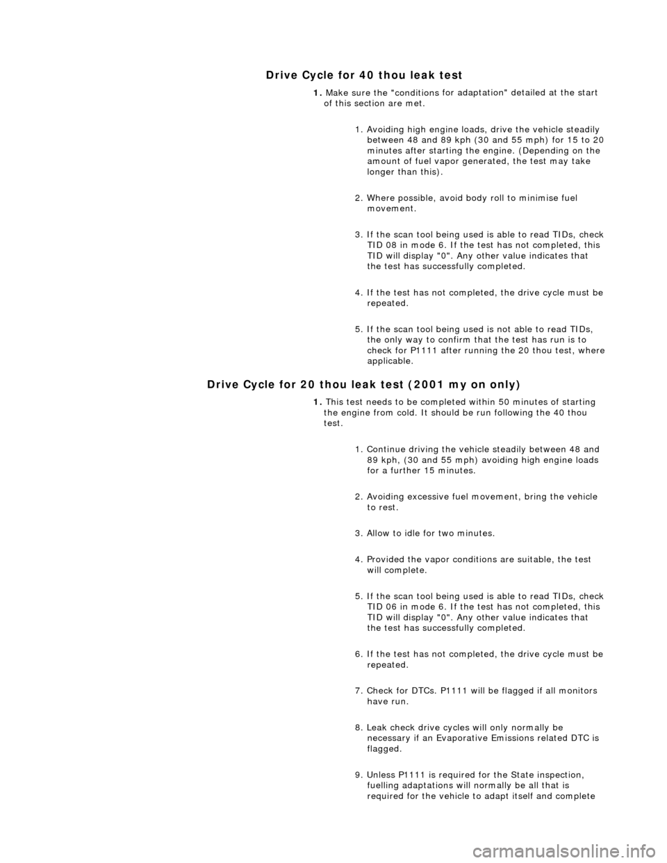
Drive Cycle for 40 thou leak test
Drive Cycle for 20 thou leak test (2001 my on only)
1. Make sure the "conditions
for ad
aptation" detailed at the start
of this section are met.
1. Avoiding high engine load s, drive the vehicle steadily
between 48 and 89 kph (30 and 55 mph) for 15 to 20
minutes after starting the engine. (Depending on the
amount of fuel vapor gene rated, the test may take
longer than this).
2. Where possible, avoid body roll to minimise fuel movement.
3. If the scan tool being used is able to read TIDs, check
TID 08 in mode 6. If the test has not completed, this
TID will display "0". Any other value indicates that
the test has successfully completed.
4. If the test has not completed, the drive cycle must be repeated.
5. If the scan tool being used is not able to read TIDs, the only way to confirm that the test has run is to
check for P1111 after running the 20 thou test, where
applicable.
1. This test needs to be completed within 50 minutes of starting
the engine from cold. It should be run following the 40 thou
test.
1. Continue driving the vehi cle steadily between 48 and
89 kph, (30 and 55 mph) avoiding high engine loads
for a further 15 minutes.
2. Avoiding excessive fuel movement, bring the vehicle to rest.
3. Allow to idle for two minutes.
4. Provided the vapor conditions are suitable, the test will complete.
5. If the scan tool being used is able to read TIDs, check
TID 06 in mode 6. If the test has not completed, this
TID will display "0". Any other value indicates that
the test has successfully completed.
6. If the test has not completed, the drive cycle must be repeated.
7. Check for DTCs. P1111 will be flagged if all monitors have run.
8. Leak check drive cycles will only normally be necessary if an Evaporative Emissions related DTC is
flagged.
9. Unless P1111 is required for the State inspection, fuelling adaptations will normally be all that is
required for the vehicle to adapt itself and complete
Page 1426 of 2490
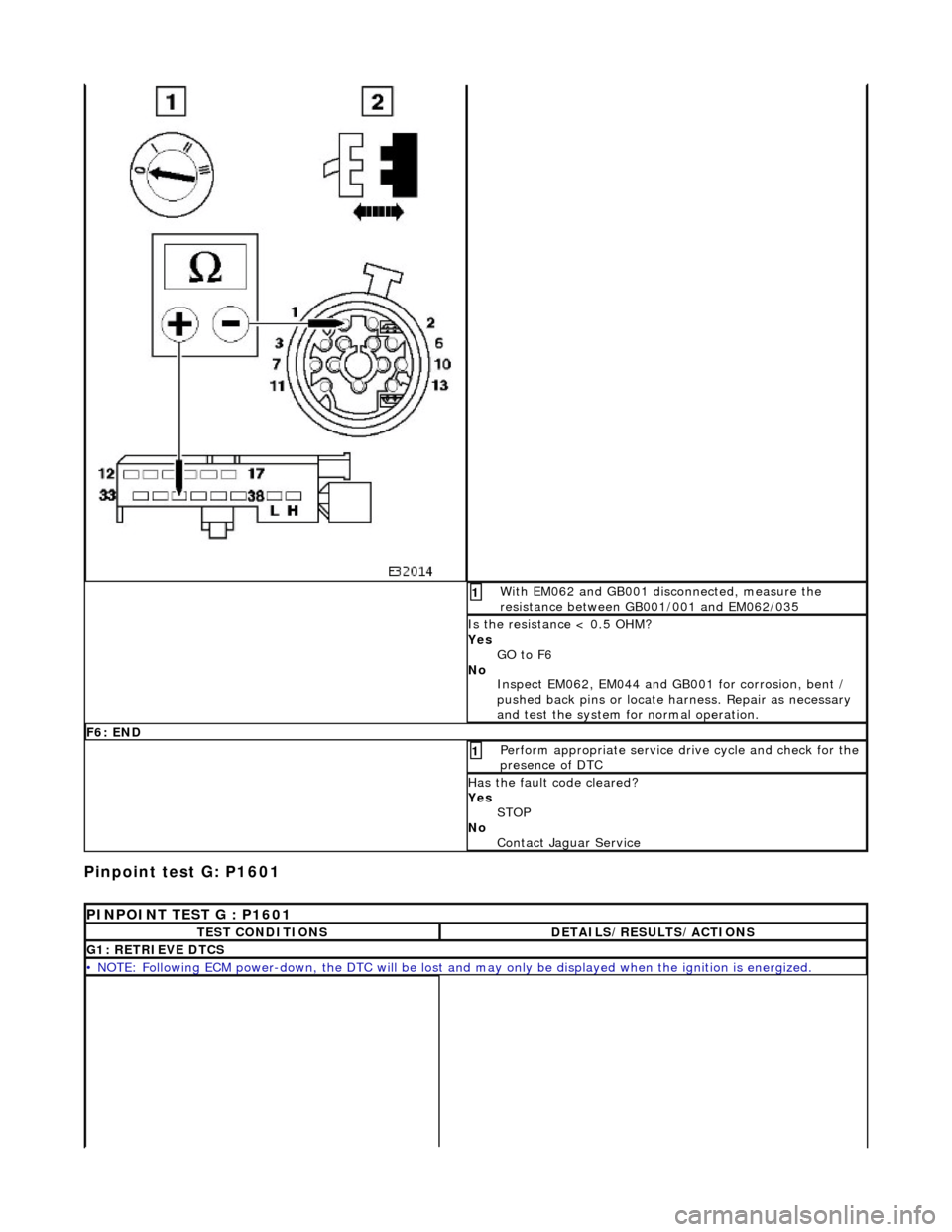
Pinpoint test G: P1601
With EM062 and GB001 disconnected, measure the
resistance between GB001/001 and EM062/035 1
Is the resistance < 0.5 OHM?
Yes GO to F6
No Inspect EM062, EM044 and GB001 for corrosion, bent /
pushed back pins or locate harness. Repair as necessary
and test the system fo r normal operation.
F6: END
Perform appropriate service drive cycle and check for the
presence of DTC 1
Has the fault code cleared?
Yes
STOP
No Contact Jaguar Service
PINPOINT TEST G : P1601
TEST CONDITIONSDETAILS/RESULTS/ACTIONS
G1: RETRIEVE DTCS
• NOTE: Following ECM power-down, the DTC will be lost and may only be displayed when the ignition is energized.
Page 1431 of 2490
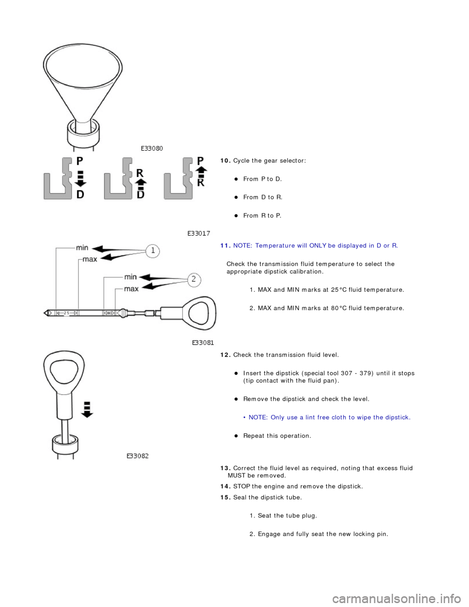
10. Cycle the gear selector:
From P to D.
From D to R.
From R to P.
11. NOTE: Temperature will ONLY be displayed in D or R.
Check the transmission fluid temperature to select the
appropriate dipstick calibration. 1. MAX and MIN marks at 25°C fluid temperature.
2. MAX and MIN marks at 80°C fluid temperature.
12. Check the transmission fluid level.
Insert the dipstick (special tool 307 - 379) until it stops
(tip contact with the fluid pan).
Remove the dipstick an d check the level.
• NOTE: Only use a lint free cloth to wipe the dipstick.
Repeat this operation.
13. Correct the fluid leve l as required, noting that excess fluid
MUST be removed.
14. STOP the engine and remove the dipstick.
15. Seal the dipstick tube.
1. Seat the tube plug.
2. Engage and fully seat the new locking pin.
Page 1481 of 2490
Automatic Transmission/Transax
le External Cont
rols - 4.0L NA V8 -
AJ27/3.2L NA V8 - AJ26 - Ki ckdown Switch Adjustment
Gen
eral Procedures
1. Ensure that the throttle cabl e is correctly adjusted, see
19.20.06.
2. See the PDU User Guide for relevant software - 1040.
3. With PDU connected, running and the message 'EXISTING
COMPONENTS TO BE TESTED YES / NO' displayed;
1. Select YES.
2. Select ENTER.
3. Follow the messages given on the screen.
4. Press ENTER on the PDU screen.
5. F
ollowing the PDU instruction;
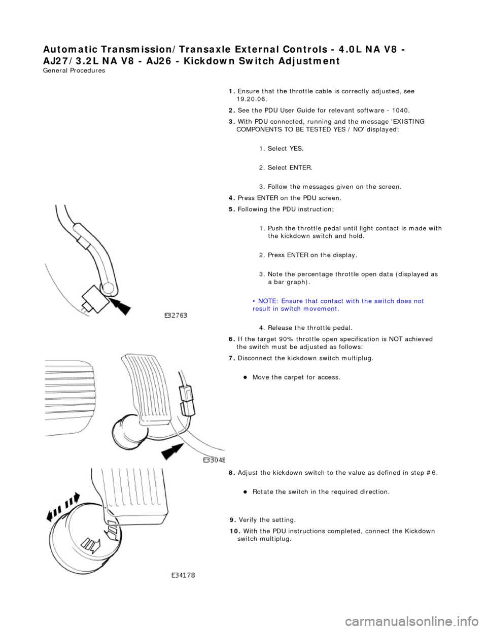
1. Push the throttle pedal until light contact is made with
the kickdown switch and hold.
2. Press ENTER on the display.
3. Note the percentage throttle open data (displayed as a bar graph).
• NOTE: Ensure that contact with the switch does not
result in switch movement.
4. Release the throttle pedal.
6. If the target 90% throttle open specification is NOT achieved
the switch must be ad justed as follows:
7. Di
sconnect the kickdown switch multiplug.
Move the car
pet for access.
8. Adjust
the kickdown switch to th
e value as defined in step #6.
R
otate the switch in th
e required direction.
9.
Veri
fy the setting.
10. With the PDU instructions completed, connect the Kickdown
switch multiplug.
Page 1509 of 2490
Automatic Transmission/Transax
le External Controls
- 4.0L SC V8 - AJ26 -
Kickdown Switch Adjustment
Gen
eral Procedures
1. Ensure that the throttle cable is correctly adjusted; refer to
Operation 19.20.06.
2. Refer to the PDU User Guide for relevant software - 1040.
3. With PDU connected, running and the message 'EXISTING
COMPONENTS TO BE TESTED YES / NO' displayed:
Select YES.
Select ENTER.
Fol
low the messages given on the screen.
4. Press ENTER on the PDU screen.
5. F
ollowing the PDU instructions:
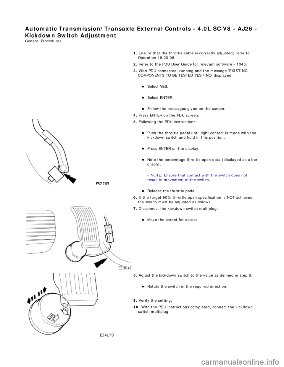
Push the throttl
e pedal until li
ght contact is made with the
kickdown switch and hold in this position.
Pres
s ENTER on the display.
No
te the percentage throttle op
en data (displayed as a bar
graph).
• NOTE: Ensure that contact with the switch does not
result in movement of the switch.
R
elease the throttle pedal.
6. If the target 90% throttle open specification is NOT achieved
the switch must be ad justed as follows.
7. Di
sconnect the kickdown switch multiplug.
Move the car
pet for access.
8. Adjust
the kickdown switch to th
e value as defined in step 6.
R
otate the switch in th
e required direction.
9.
Veri
fy the setting.
10. With the PDU instructions completed, connect the kickdown
switch multiplug.