1998 JAGUAR X308 display
[x] Cancel search: displayPage 438 of 2490

Make sure the ignition is off. 1
Disc
onnect the ABS module connector, LF27.
2
M
e
asure the resistance between LF27, pin 17 (W) and FL01, pin 02 (W).
3
I
s
the resistance less than 5 ohms?
Yes GO to C3
.
No
Re
pair the high resistance circui
t. This circuit includes intermed iate connector, LF02. Refer to the
electrical guides. Clear the DTC, check for normal operation.
C3: CH
ECK THE WSS RETURN CIRCUIT CONTINUITY
Measure
the resistance between LF27, pin 18 (R) and FL01, pin 01 (R).
1
Is
the resistance less than 5 ohms?
Yes The WSS and circuits are OK. Check for DTCs indicating a possible module failure.
No Repair the high resistance circui t. This circuit includes intermediate connector, LF01. Refer to the
electrical guides. Clear the DTC, check for normal operation.
PI
NPOINT TEST D : CHECK THE RIGH
T-HAND REAR WSS AND CIRCUITS
•
NOTE: Check connectors and pins for damage/corrosion
(see visual inspection).
• NO
TE: Check the WSS ring condition, whee
l bearing etc. Before beginning pinpoint test s refer to the visual inspection.
TES
T
CONDITIONS
D E
TAILS/RESULTS/ACTIONS
D1: CHECK
THE WSS OUTPUT
Disc
onne
ct the ABS sensor connector, RA02.
1
Connec
t
a multimeter set
to read alternating curr ent volts (AC volts) between pins 1 and 2 of the
sensor.
2
Spin
the wheel by hand and check the meter display.
3
Doe
s
the sensor generate a voltage?
Yes GO to D2
.
No
If
the WSS ring is in good condition, install a new WSS.
REFER to: Rear Wheel Speed Sensor
(206-0
9 Anti-Lock Control, Removal and Installation).
D
2
: CHECK THE WSS SIGNAL CIRCUIT CONTINUITY
Make sure the ignition is off. 1
Disc
onnect the ABS module connector, LF27.
2
Measure t
he resistance between LF27
, pin 07 (O) and RA02, pin 01 (O).
3
Is
the resistance less than 5 ohms?
Yes GO to D3
.
No Re
pair the high resistance circui
t. This circuit includes intermed iate connector, LA02. Refer to the
electrical guides. Clear the DTC, check for normal operation.
D3:
CHECK THE WSS RETURN CIRCUIT CONTINUITY
Meas
ure t
he resistance between LF27
, pin 06 (Y) and RA02, pin 02 (Y).
1
Is
the resistance less than 5 ohms?
Yes The WSS and circuits are OK. Check for DTCs indicating a possible module failure.
No Repair the high resistance circui t. This circuit includes intermediate connector, CA09. Refer to the
electrical guides. Clear the DTC, check for normal operation.
PI
NPOINT TEST E : CHECK THE LEFT-HAND REAR WSS AND CIRCUITS
•
NOTE: Check connectors and pins for damage/corrosion
(see visual inspection).
• NO
TE: Check the WSS ring condition, whee
l bearing etc. Before beginning pinpoint test s refer to the visual inspection.
TES
T
CONDITIONS
D E
TAILS/RESULTS/ACTIONS
E1
: CHECK THE W
SS OUTPUT
Disc
onne
ct the ABS sensor connector, LA02.
1
Connec
t
a multimeter set
to read alternating curr ent volts (AC volts) between pins 1 and 2 of the
sensor.
2
Page 439 of 2490

Spin
the wheel by hand and check the meter display.
3
Doe
s the sensor generate a voltage?
Yes GO to E2
.
No
If the WSS ring is in good condition, install a new WSS.
REFER to: Rear Wheel Speed Sensor
(20
6-09 Anti-Lock Control, Removal and Installation).
E2
: CHECK THE WSS SIGNAL CIRCUIT CONTINUITY
Make sure the ignition is off. 1
Di
sconnect the ABS module connector, LF27.
2
Meas
ure the resistance between LF27
, pin 21 (U) and LA02, pin 01 (U).
3
I
s the resistance less than 5 ohms?
Yes GO to E3
.
No
Repair the high resistance circui t. This circuit includes intermediate connector, LA02. Refer to the
electrical guides. Clear the DTC, check for normal operation.
E3
: CHECK THE WSS RETURN CIRCUIT CONTINUITY
Meas
ure the resistance between LF27
, pin 22 (U) and LA02, pin 02 (U).
1
I
s the resistance less than 5 ohms?
Yes The WSS and circuits are OK. Check for DTCs indicating a possible module failure.
No Repair the high resistance circui t. This circuit includes intermediate connector, CA29. Refer to the
electrical guides. Clear the DTC, check for normal operation.
P
INPOINT TEST F : CONT
ROLLER AREA NETWORK (CAN) INTEGRITY TEST
TE
ST
CONDITIONS
D
ETAILS/RESULTS/ACTIONS
F
1: CHECK THE NETWORK INTEGRITY
FROM THE DIAGNOSTIC SOCKET
M
easure the resistance between pins 06 (Y) and 14 (G) of the diagnostic socket.
1
I
s the resistance 60 ohms?
Yes The CAN system is OK. Check for DTCs indicating a fault elsewhere.
No Check the CAN system for open an d short circuits. Refer to the electrical guides. Clear the DTC,
check for normal operation.
Page 935 of 2490
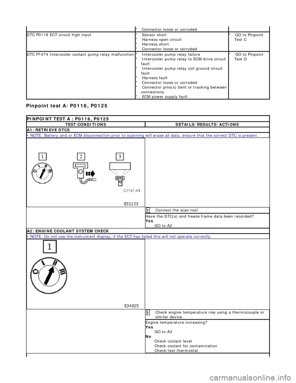
Pinpoint test
A: P0116, P0125
Connector
loose or corroded
*
D
TC P0118 ECT circuit high input
Sensor short
Harness open circui
t
Harness short
Connector loose or corroded
*
*
*
*
GO to Pinpoint
Test C
*
D
TC P1474 Intercooler coolant pump relay malfunction
Intercooler pump relay
failure
Intercooler pump relay to ECM drive circuit
fault Intercooler pump relay coil ground circuit
fault Harness fault
Connector loose or corroded
Connector pins(s) bent or tracking between
connections ECM power supply fault
*
*
*
*
*
*
*
GO to Pinpoint
Test D
*
P
INPOINT TEST A : P0116, P0125
T
EST CONDITIONS
D
ETAILS/RESULTS/ACTIONS
A1
: RETRIEVE DTCS
•
NOTE: Battery and or ECM disconnection prior to scanning wi
ll erase all data, ensure that the correct DTC is present.
Conne
ct the scan tool
1
Have the DTC(s) and fr
eeze
frame data been recorded?
Yes GO to A2
A2: ENGINE
COOLANT SYSTEM CHECK
•
NOTE: Do not use the instrument display, if th
e ECT has failed this will not operate correctly.
Chec
k engine temperature rise using a thermocouple or
similar device.
1
Engine
temperature increasing?
Yes GO to A3
No Check coolant level
Check coolant for contamination
Check/test thermostat
Page 1020 of 2490
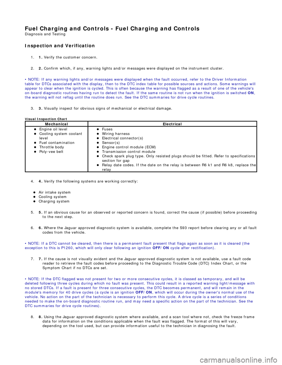
Fuel Char
ging and Controls - Fuel Charging and Controls
D
iagn
osis and Testing
I
n
spection and Verification
1.
1. Veri fy the customer concern.
2. 2. Confi
rm which, if any, warning li
ghts and/or messages were displayed on the instrument cluster.
• NOTE: If any warning lights and/or me ssages were displayed when the fault occurred, refer to the Driver Information
table for DTCs associated with the display, then to the DTC index table for possible sources and actions. Some warnings will
appear to clear when the ignition is cycl ed. This is often because the warning has flagged as a resu lt of one of the vehicle's
on-board diagnostic routines having run to detect the fault. If the same routine is not run when the ignition is switched ON,
the warning will not reflag until the routine does run. See the DTC summaries for drive cycle routines.
3. 3. Visually inspect for obvious signs of mechanical or electrical damage.
Vi
sual Inspection Chart
4.
4. Veri fy the foll
owing syst
ems are working correctly:
Air intake
system
Cooling system
Charging system
5. 5. If
an obvious cause for an observed or
reported concern is found, correct th e cause (if possible) before proceeding
to the next step.
6. 6. Where the Jaguar approved diagnostic sy stem is available, complete the S93 report before clearing any or all fault
codes from the vehicle.
• NOTE: If a DTC cannot be cleared, then there is a permanent fault present that flag s again as soon as it is cleared (the
exception to this is P1260, which will only clear following an ignition OFF/ON cycle after rectification).
7. 7. If the cause is not visually evident and the Jaguar approv ed diagnostic system is not available, use a fault code
reader to retrieve the fault codes be fore proceeding to the Diagnostic Trou ble Code (DTC) Index Chart, or the
Symptom Chart if no DTCs are set.
• NOTE: If the DTC flagged was not present for two or more co nsecutive cycles, it is classed as temporary, and will be
deleted following three cycl es during which no fault was present. This could result in a reported wa rning light/message with
no stored DTCs. If a fault is present for three consecutive cycles, the DTC becomes permanent, and will remain in the
module's memory for 40 drive cycl es (a cycle is an ignition OFF/ON, which will occur during the owner's normal use of the
vehicle. No action on the part of the technician is necessary to perform this cycle. A drive cycle is a series of conditions
needed to make the on-board diagnostic ro utine run, and may need a specific action on the part of the technician. See the
DTC summaries for drive cycle routines).
8. 8. Using the Jaguar approved diagnostic system where available, and a scan tool where not, check the freeze frame
data for information on the conditions applicable when the fault was flagged. The format of this will vary,
depending on the tool used, but can pr ovide information useful to the technician in diagnosing the fault.
MechanicalElectrical
Engine
oil level
Coo
ling system coolant
lev
el
Fuel contamination
Throttle body Poly-ve
e belt
Fu
ses
W
i
ring harness
E
l
ectrical connector(s)
Sens
o
r(s)
Engine
control module (E
CM)
Tran
s
mission control module
Check spark plu
g type. Only r
e
sisted plugs should be fitted. Refer to specifications
section for gap
Relay date codes. I
f the date on the rela
y is between R6 k1 and R6 k8, replace the
relay
Page 1023 of 2490
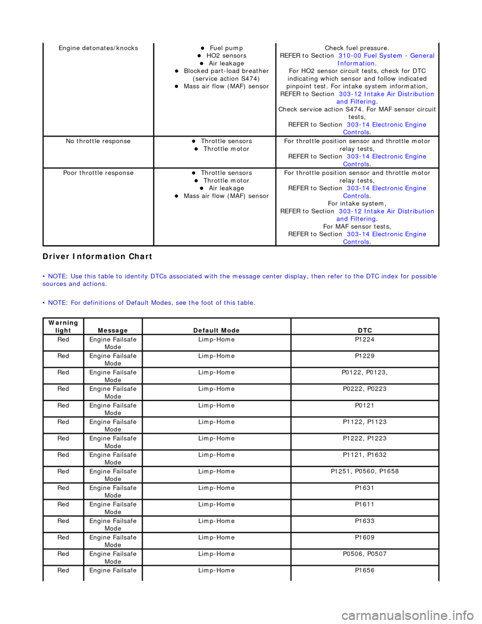
Driver Informa
tion Chart
•
NOTE: Use this table to identify DTCs associated with the me
ssage center display, then refer to the DTC index for possible
sources and actions.
• NOTE: For definitions of Default Modes, see the foot of this table.
Engine deton
ates/knocks
Fue
l pump
HO2 sensors Air leakage Blocked part-load breather
(
service action S474)
Mass ai
r flow (MAF) sensor
Chec
k fuel pressure.
REFER to Section 310
-00
Fuel System
- Gen
eral
Informati
on
.
F
or HO2 sensor circuit
tests, check for DTC
indicating which sensor and follow indicated
pinpoint test. For intake system information,
REFER to Section 303
-1
2 Intake Air Distribution
and F
iltering
.
Check service
action S474. For MAF sensor circuit
tests,
REFER to Section 303
-14 Elec
tronic Engine
Controls.
No
throttle response
Throttl
e sensors
Throttl
e motor
F
or throttle position se
nsor and throttle motor
relay tests,
REFER to Section 303
-14 Elec
tronic Engine
Controls.
Poor throttle responseThrottl
e sensors
Throttl
e motor
Air leakage Mass ai
r flow (MAF) sensor
F
or throttle position se
nsor and throttle motor
relay tests,
REFER to Section 303
-14 Elec
tronic Engine
Controls.
Fo
r intake system,
REFER to Section 303
-1
2 Intake Air Distribution
and F
iltering
.
For MAF
sensor tests,
REFER to Section 303
-14 Elec
tronic Engine
Controls.
Warning
lightMess
age
De
fault Mode
DT
C
Re
d
Engine
Failsafe
Mode
Lim
p-Home
P1224
Re
d
Engine
Failsafe
Mode
Lim
p-Home
P1229
Re
d
Engine
Failsafe
Mode
Lim
p-Home
P01
22, P0123,
Re
d
Engine
Failsafe
Mode
Lim
p-Home
P02
22, P0223
Re
d
Engine
Failsafe
Mode
Lim
p-Home
P0121
Re
d
Engine
Failsafe
Mode
Lim
p-Home
P11
22, P1123
Re
d
Engine
Failsafe
Mode
Lim
p-Home
P12
22, P1223
Re
d
Engine
Failsafe
Mode
Lim
p-Home
P11
21, P1632
Re
d
Engine
Failsafe
Mode
Lim
p-Home
P12
51, P0560, P1658
Re
d
Engine
Failsafe
Mode
Lim
p-Home
P1631
Re
d
Engine
Failsafe
Mode
Lim
p-Home
P1611
Re
d
Engine
Failsafe
Mode
Lim
p-Home
P1633
Re
d
Engine
Failsafe
Mode
Lim
p-Home
P1609
Re
d
Engine
Failsafe
Mode
Lim
p-Home
P05
06, P0507
Re
d
Engine
Failsafe
Lim
p-Home
P1656
Page 1050 of 2490
Power Assisted Steering Pump Drive
The power assisted steering pump pull
ey
is located on the left side, above the air-conditioning compressor.
Generator Dr
ive
The genera
tor is fitted on the
right hand accessory mounting.
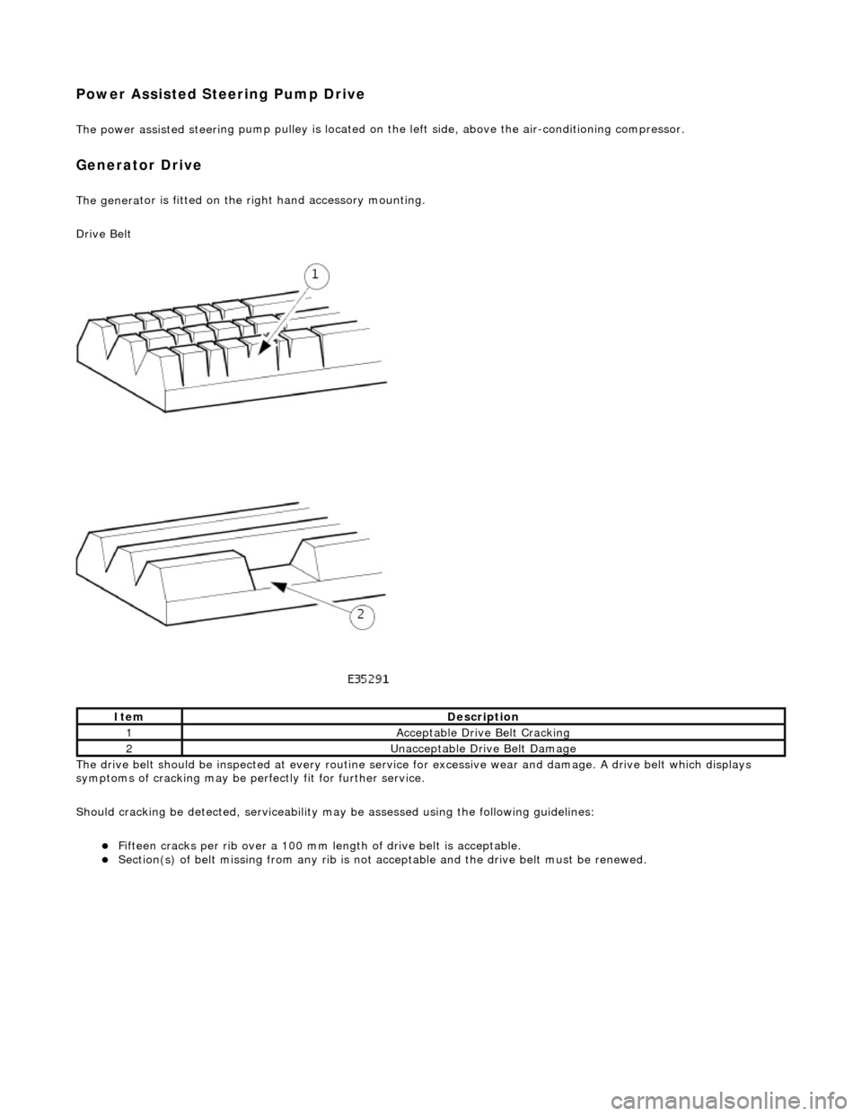
Drive Belt
The drive belt should be inspected at every routine service for excessive wear and damage. A drive belt which displays
symptoms of cracking may be pe rfectly fit for further service.
Should cracking be detected, serviceability ma y be assessed using the following guidelines:
Fi
fteen cracks per rib over a 100 mm le
ngth of drive belt is acceptable.
Sec
tion(s) of belt missing from an
y rib is not acceptable and the drive belt must be renewed.
Ite
m
De
scr
iption
1Ac
c
eptable Drive Belt Cracking
2Unacceptable Drive Belt Damage
Page 1077 of 2490
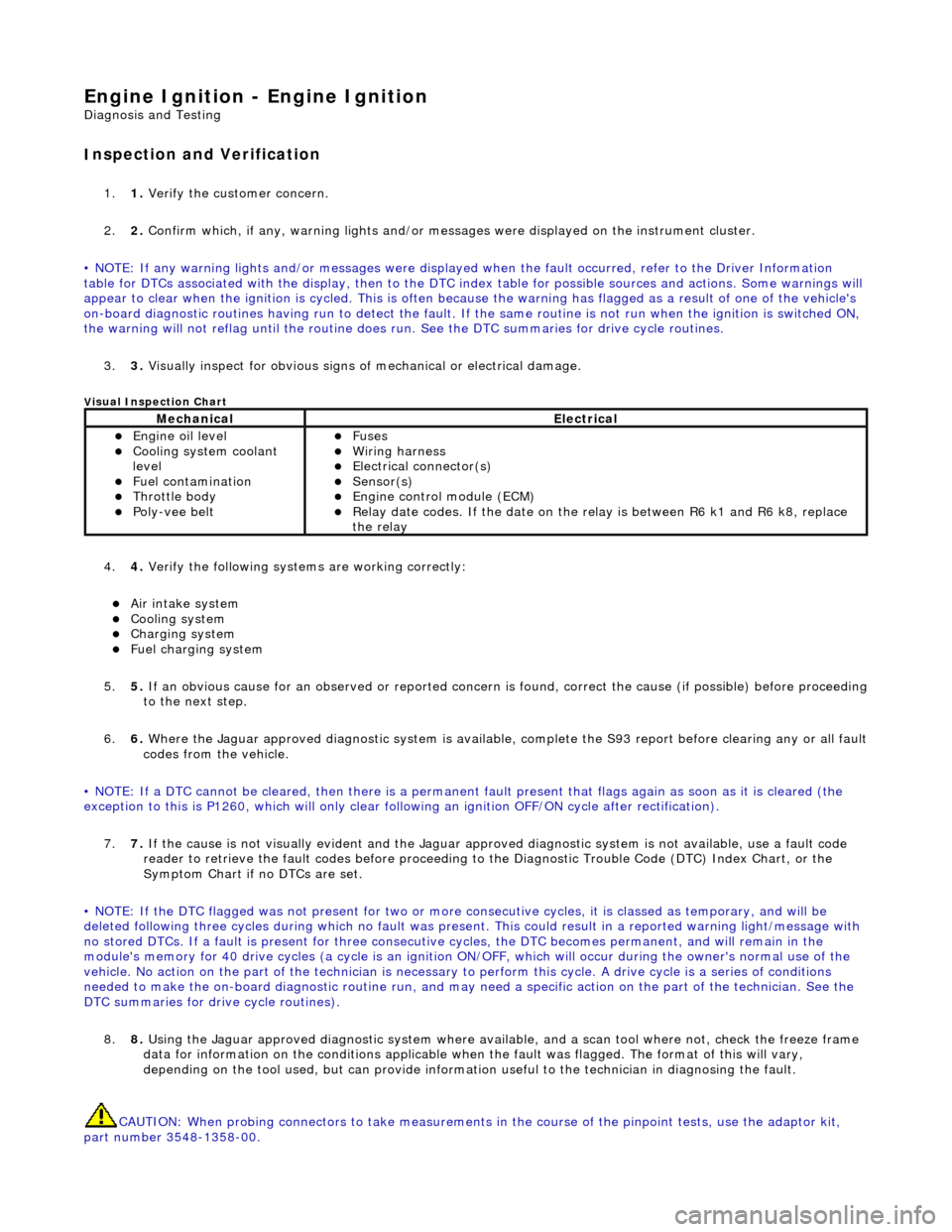
Engine Igni
tion -
Engine Ignition
D
iagnosis and Testing
I
nspection and Verification
1.
1. Veri
fy the customer concern.
2. 2. Confirm which, if any, warning li ghts and/or messages were displayed on the instrument cluster.
• NOTE: If any warning lights and/or me ssages were displayed when the fault occurred, refer to the Driver Information
table for DTCs associated with the display, then to the DTC index table for possible sources and actions. Some warnings will
appear to clear when the ignition is cycl ed. This is often because the warning has flagged as a resu lt of one of the vehicle's
on-board diagnostic routines having run to detect the fault. If the same routine is not run when the ignition is switched ON,
the warning will not reflag until the routine does run. See the DTC summaries for drive cycle routines.
3. 3. Visually inspect for obvious signs of mechanical or electrical damage.
V
isual Inspection Chart
4.
4. Veri
fy the following syst
ems are working correctly:
Air in
take system
Coo
ling system
Charging system
F
uel charging system
5. 5. If an obvious cause for an observed or reported concern is found, correct the cause (if possible) before proceeding
to the next step.
6. 6. Where the Jaguar approved diagnostic sy stem is available, complete the S93 report before clearing any or all fault
codes from the vehicle.
• NOTE: If a DTC cannot be cleared, then there is a permanent fault present that flag s again as soon as it is cleared (the
exception to this is P1260, which will only clear following an ignition OFF/ON cycle after rectification).
7. 7. If the cause is not visually evident and the Jaguar approv ed diagnostic system is not available, use a fault code
reader to retrieve the fault codes be fore proceeding to the Diagnostic Trou ble Code (DTC) Index Chart, or the
Symptom Chart if no DTCs are set.
• NOTE: If the DTC flagged was not present for two or more co nsecutive cycles, it is classed as temporary, and will be
deleted following three cycl es during which no fault was present. This could result in a reported wa rning light/message with
no stored DTCs. If a fault is present for three consecutive cycles, the DTC becomes permanent, and will remain in the
module's memory for 40 drive cycles (a cy cle is an ignition ON/OFF, which will occur during the owner's normal use of the
vehicle. No action on the part of the technician is necessary to perform this cycle. A drive cycle is a series of conditions
needed to make the on-board diagnostic ro utine run, and may need a specific action on the part of the technician. See the
DTC summaries for driv e cycle routines).
8. 8. Using the Jaguar approved diagnostic system where available, and a scan tool where not, check the freeze frame
data for information on the conditions applicable when the fault was flagged. The format of this will vary,
depending on the tool used, but can pr ovide information useful to the technician in diagnosing the fault.
CAUTION: When probing connectors to take measurements in the course of the pinpoint tests, use the adaptor kit,
part number 3548-1358-00.
MechanicalElectrical
Engi
ne oil level
Coo
ling system coolant
level
Fuel contamination
Throttle body Poly
-vee belt
F
uses
W
iring harness
E
lectrical connector(s)
Sens
or(s)
Engine
control module (ECM)
Relay date codes.
If the date on the relay is between R6 k1 and R6 k8, replace
the relay
Page 1080 of 2490
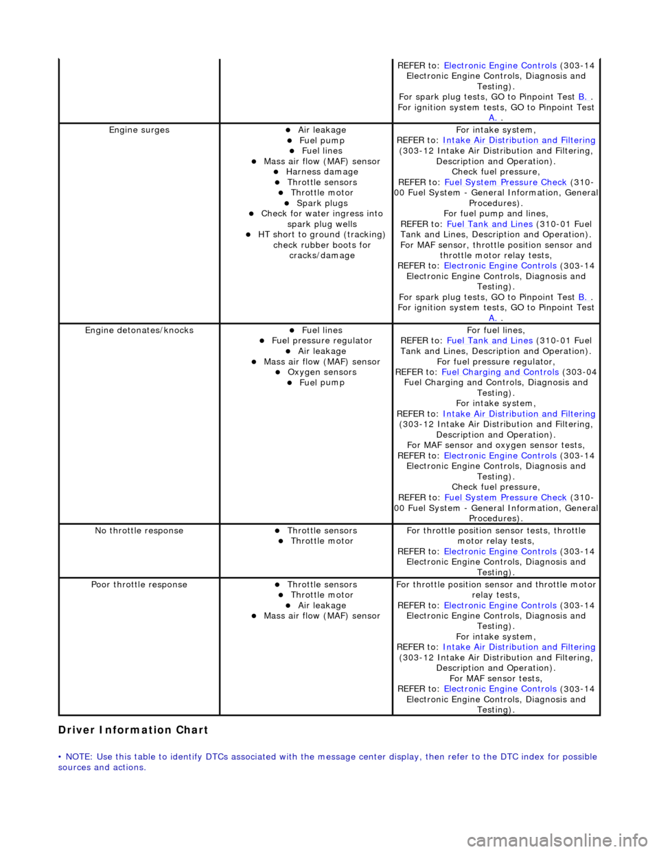
Driver Information
Chart
•
NOTE: Use this table to identify DTCs associated with the me
ssage center display, then refer to the DTC index for possible
sources and actions.
REF E
R to:
Electronic Engine Controls
(303
-14
Electronic Engine Co ntrols, Diagnosis and
Testing).
For spark plug tests, GO to Pinpoint Test B.
.
For ign i
tion system tests, GO to Pinpoint Test
A.
.
Engine s
urges
Air leakage
Fue
l
pump
Fue
l
lines
Mass ai
r fl
ow (MAF) sensor
Harness damage Throttl
e
sensors
Throttl
e
motor
Spark plugs
Check fo
r water ingress into
spark plug wells
HT short to ground (tracking) check rubber
boots for
cracks/damage
Fo r
intake system,
REFER to: Intake Air Distribution and Filtering
(30 3
-12 Intake Air Distribution and Filtering,
Description and Operation). Check fuel pressure,
REFER to: Fuel System Pressure Check
(310
-
00 Fuel System - Genera l Information, General
Procedures).
For fuel pump and lines,
REFER to: Fuel Tank and Lines
(310
-01 Fuel
Tank and Lines, Description and Operation).
For MAF sensor, throttle position sensor and
throttle motor relay tests,
REFER to: Electronic Engine Controls
(303
-14
Electronic Engine Co ntrols, Diagnosis and
Testing).
For spark plug tests, GO to Pinpoint Test B.
.
For ign i
tion system tests, GO to Pinpoint Test
A.
.
Engine detonates/k
nocks
Fue
l
lines
F
u
el pressure regulator
Air leakage
Mass air fl
ow (MAF) sensor
O
xygen senso
rs
Fue
l
pump
F
o
r fuel lines,
REFER to: Fuel Tank and Lines
(310
-01 Fuel
Tank and Lines, Description and Operation).
For fuel pressure regulator,
REFER to: Fuel Charging and Controls
(303
-04
Fuel Charging and Controls, Diagnosis and Testing).
For intake system,
REFER to: Intake Air Distribution and Filtering
(30 3
-12 Intake Air Distribution and Filtering,
Description and Operation).
For MAF sensor and oxyg en sensor tests,
REFER to: Electronic Engine Controls
(303
-14
Electronic Engine Co ntrols, Diagnosis and
Testing).
Check fuel pressure,
REFER to: Fuel System Pressure Check
(310
-
00 Fuel System - Genera l Information, General
Procedures).
No t
hrottle response
Throttl
e
sensors
Throttl
e
motor
Fo
r th
rottle position sensor tests, throttle
motor relay tests,
REFER to: Electronic Engine Controls
(303
-14
Electronic Engine Co ntrols, Diagnosis and
Testing).
Poor throttle responseThrottl e
sensors
Throttl
e
motor
Air leakage Mass air fl
ow (MAF) sensor
F
or throttl
e position se
nsor and throttle motor
relay tests,
REFER to: Electronic Engine Controls
(303
-14
Electronic Engine Co ntrols, Diagnosis and
Testing).
For intake system,
REFER to: Intake Air Distribution and Filtering
(30 3
-12 Intake Air Distribution and Filtering,
Description and Operation). For MAF sensor tests,
REFER to: Electronic Engine Controls
(303
-14
Electronic Engine Co ntrols, Diagnosis and
Testing).