1998 JAGUAR X308 display
[x] Cancel search: displayPage 1828 of 2490
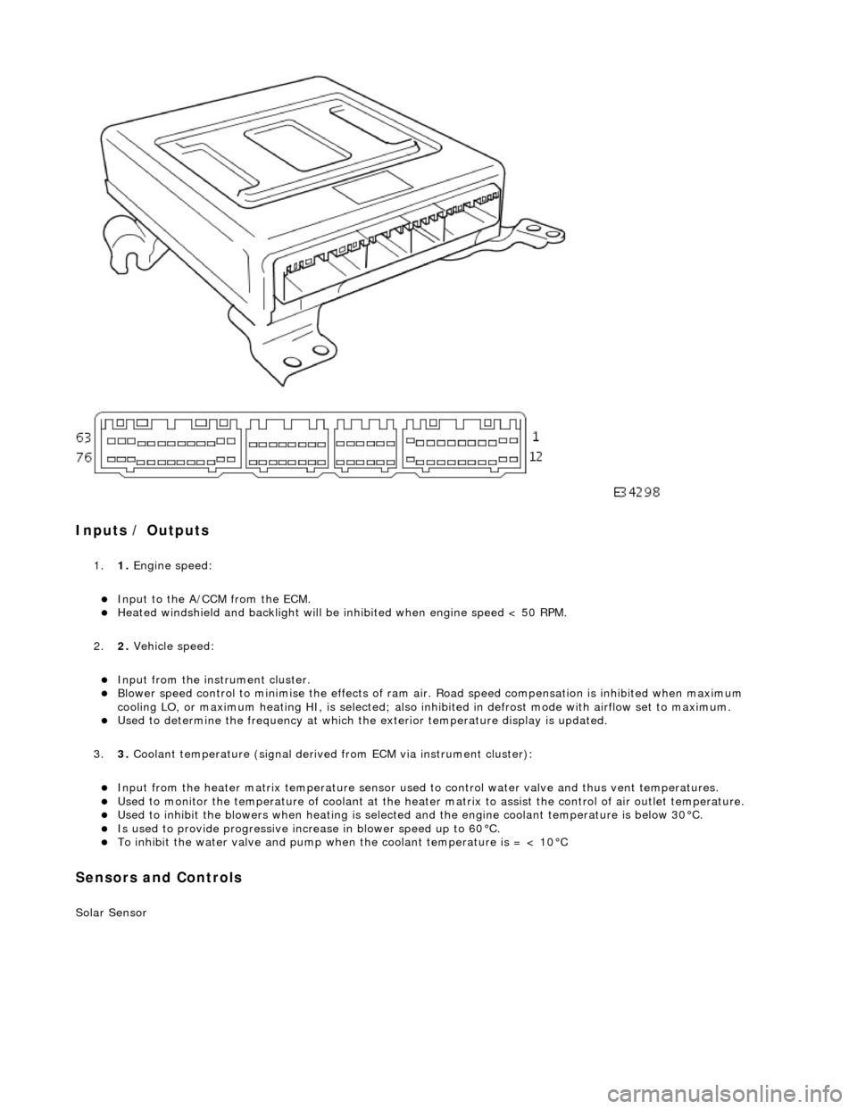
Inputs / Outputs
1.1. Engine speed:
Input to the A/CCM from the ECM. Heated windshield and backli ght will be inhibited when engine speed < 50 RPM.
2. 2. Vehicle speed:
Input from the instru ment cluster. Blower speed control to minimise the effects of ram ai r. Road speed compensation is inhibited when maximum
cooling LO, or maximum heating HI, is selected; also inhi bited in defrost mode with airflow set to maximum.
Used to determine the frequency at which the exterior temperature display is updated.
3. 3. Coolant temperature (signal derived from ECM via instrument cluster):
Input from the heater matrix temperature sensor used to control water valve and thus vent temperatures. Used to monitor the temperature of coolant at the heater matrix to assist the control of air outlet temperature. Used to inhibit the blowers when heating is selected and the engine coolant temperature is below 30°C. Is used to provide progressive increase in blower speed up to 60°C. To inhibit the water valve and pump when the coolant temperature is = < 10°C
Sensors and Controls
Solar Sensor
Page 1830 of 2490
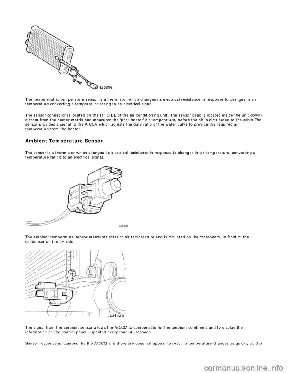
The heater matrix temperature sensor is a thermistor which changes its electrical resistance in response to changes in air
temperature converting a temperature rating to an electrical signal.
The sensor connector is located on the RH SIDE of the air conditioning unit. The sensor bead is located inside the unit down-
stream from the heater matrix and measures the 'post-heater' air temperature, before the air is distribu ted to the cabin The
sensor provides a signal to the A/CCM which adjusts the duty ratio of the water valve to provide the required air
temperature from the heater.
Ambient Temperature Sensor
The sensor is a thermistor which changes its electrical resistance in response to changes in air temperature, converting a
temperature rating to an electrical signal.
The ambient temperature sensor measures exterior air temper ature and is mounted on the crossbeam, in front of the
condenser on the LH side.
The signal from the ambient sensor allo ws the A/CCM to compensate for the ambient conditions and to display the
information on the control panel - updated every four (4) seconds.
Sensor response is 'damped' by the A/CCM and ther efore does not appear to react to temperature chan
ges as quickly as the
Page 1832 of 2490
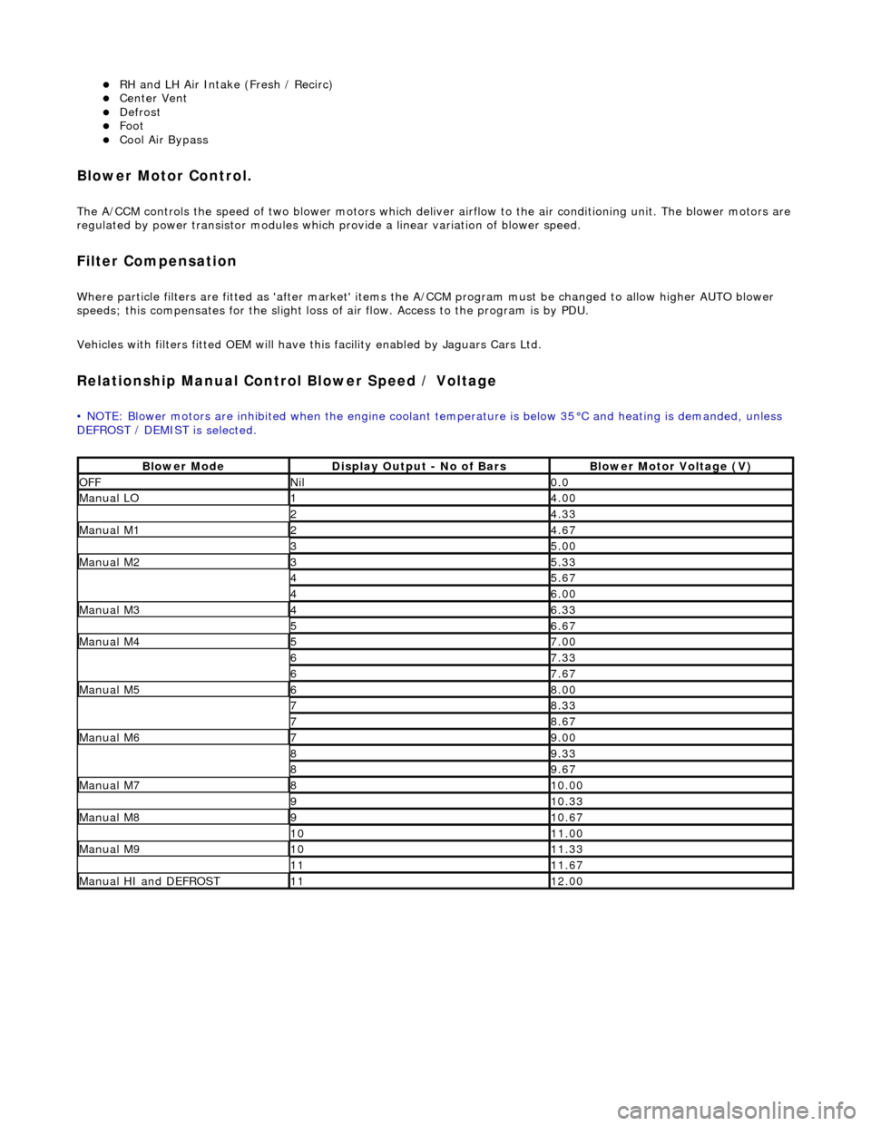
RH and LH Air Intake (Fresh / Recirc) Center Vent Defrost Foot Cool Air Bypass
Blower Motor Control.
The A/CCM controls the speed of two blower motors which deliver airflow to the air conditioning unit. The blower motors are
regulated by power transistor modules which pr ovide a linear variation of blower speed.
Filter Compensation
Where particle filters are fitted as 'after market' items the A/CCM program must be changed to allow higher AUTO blower
speeds; this compensates for the slight loss of air flow. Access to the program is by PDU.
Vehicles with filters fitted OEM will have this facility enabled by Jaguars Cars Ltd.
Relationship Manual Contro l Blower Speed / Voltage
• NOTE: Blower motors are inhibited when the engine coolant temperature is below 35°C and heating is demanded, unless
DEFROST / DEMIST is selected.
Blower ModeDisplay Output - No of BarsBlower Motor Voltage (V)
OFFNil0.0
Manual LO14.00
24.33
Manual M124.67
35.00
Manual M235.33
45.67
46.00
Manual M346.33
56.67
Manual M457.00
67.33
67.67
Manual M568.00
78.33
78.67
Manual M679.00
89.33
89.67
Manual M7810.00
910.33
Manual M8910.67
1011.00
Manual M91011.33
1111.67
Manual HI and DEFROST1112.00
Page 1836 of 2490
System Self-test
Control Panel Interrogation Procedure
The control panel has a self-diagnosis feature, and is capable of displaying and clearing stored fault codes.
Climate control is an integrated system, therefore it is recommended that the PDU is used for fault diagnosis. The fault
codes displayed with the control panel self -diagnosis feature are not as comprehensive as those of the PDU. The PDU will
display the relevant fault code, fault co de description and information of the system peripherals at the time the fault
occurred.
Fault Code Extraction and Deletion Procedure
Error information is stored in the A/CCM up to a maximum of 5 faults. Should a sensor fault occur there will be an audible
beep and the message Er will be displayed on the control panel display for 5 seco nds after ignition on. Please note that this
will happen only once in any ignition switch cycle. The error source may be accessed by the following procedure
This procedure must be completed through one complete cycle, 1 through 6
• NOTE: * Actuator codes do NOT equate to system fault codes.
• NOTE: Only codes 11, 15 and 21 (see Fault Code List ing) will cause audible beep and 'Er' display.
• NOTE: If '0' is displayed, there are no stored faul t codes, wait 30 seconds to allow system self-test.
The control panel display will flash repeatedly indicating a list of two digit numbers (see table for code analysis). Should a code be displayed accompanied by an audible beep, the fault is current and therefore still present within
the system. A code displayed without an accompanying 'bee p' indicates a fault had previously occurred but is not
present within the system.
• NOTE: It is advisable to check all areas indicated with cleared fault codes. Such faults may re-occur if intermittent
problems are present in the system.
To delete stored and cleared fault codes press 'R' and 'FAC E' buttons simultaneously. After investigating and correcting all stored faults, press the 'Push Off' button to restore normal operation with
default panel settings, ie AUTO at 24°C.
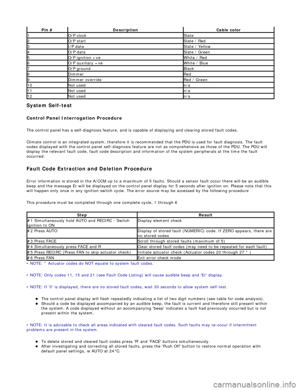
Pin #DescriptionCable color
1O/P clockSlate
2O/P startSlate / Red
3I/P dataSlate / Yellow
4O/P dataSlate / Green
5O/P ignition +veWhite / Red
6O/P auxiliary +veWhite / Blue
7O/P groundBlack
8DimmerRed
9Dimmer overrideRed / Green
10Not usedn/a
11Not usedn/a
12Not usedn/a
StepResult
#1 Simultaneously hold AU TO and RECIRC - Switch
ignition to ONDisplay element check
#2 Press AUTODisplay of stored fault (NUMERIC) code. If ZERO appears, there are
no stored codes
#3 Press FACEScroll through stored faults (maximum of 5)
#4 Simultaneously press FACE and RClear stored fault codes (may need to be repeated for each fault)
#5 Press RECIRC (Press FAN to skip actuator check)Initiate actuator check (Actuator codes 20 through 27 * )
#6 Press FANExit error check mode
Page 1838 of 2490
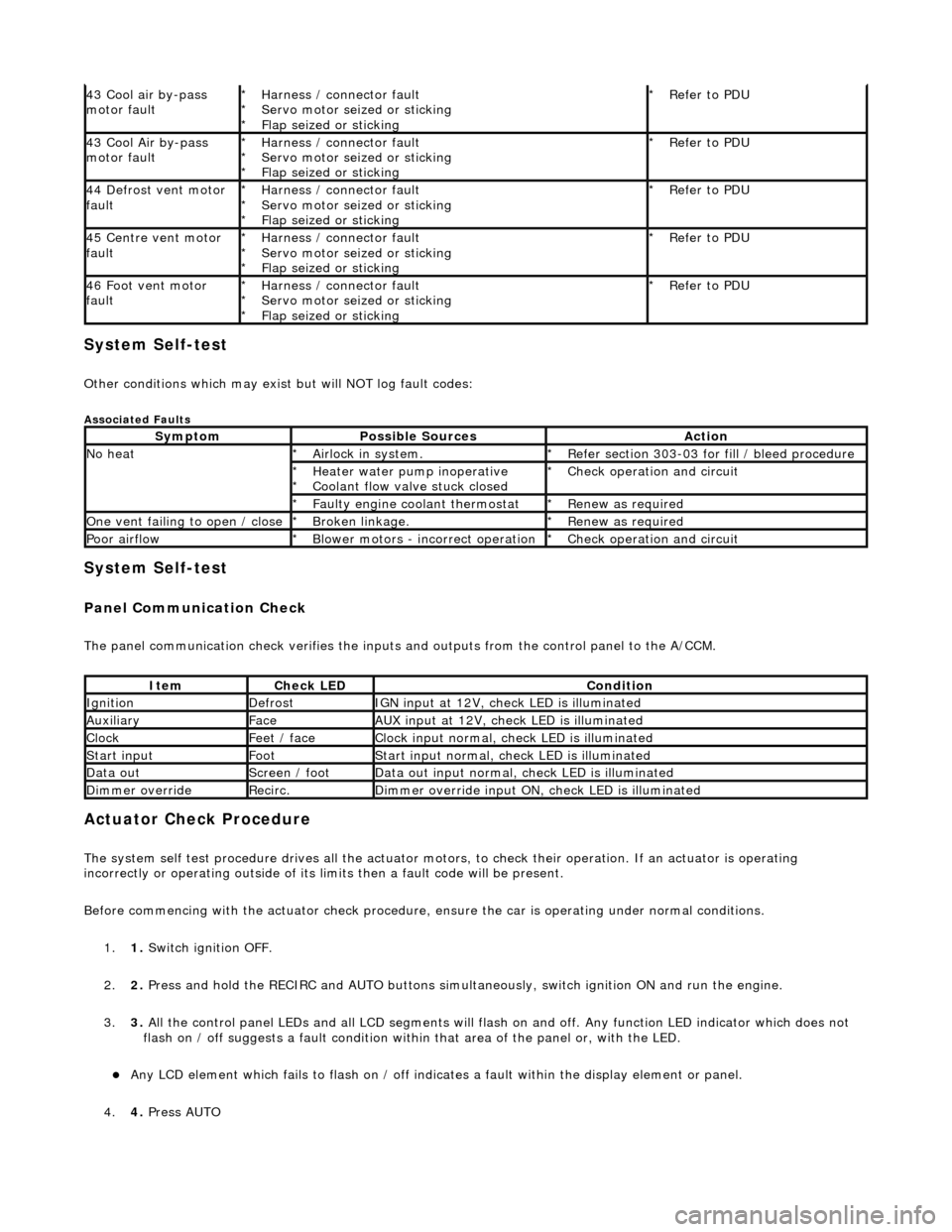
System Self-test
Other conditions which may exist but will NOT log fault codes:
Associated Faults
System Self-test
Panel Communication Check
The panel communication check veri fies the inputs and outputs from the control panel to the A/CCM.
Actuator Check Procedure
The system self test procedure drives all the actuator moto rs, to check their operation. If an actuator is operating
incorrectly or operating outside of its limi ts then a fault code will be present.
Before commencing with the actuator check procedure, ensure the ca r is operating under normal conditions.
1. 1. Switch ignition OFF.
2. 2. Press and hold the RECIRC and AUTO buttons simult aneously, switch ignition ON and run the engine.
3. 3. All the control panel LEDs and all LCD segments will flas h on and off. Any function LED indicator which does not
flash on / off suggests a fault condition within that area of the panel or, with the LED.
Any LCD element which fails to flash on / off indicates a fault within the display element or panel.
4. 4. Press AUTO
43 Cool air by-pass
motor faultHarness / connector fault
Servo motor seized or sticking
Flap seized or sticking
*
*
*Refer to PDU
*
43 Cool Air by-pass
motor faultHarness / connector fault
Servo motor seized or sticking
Flap seized or sticking
*
*
*Refer to PDU
*
44 Defrost vent motor
faultHarness / connector fault
Servo motor seized or sticking
Flap seized or sticking
*
*
*Refer to PDU
*
45 Centre vent motor
faultHarness / connector fault
Servo motor seized or sticking
Flap seized or sticking
*
*
*Refer to PDU
*
46 Foot vent motor
faultHarness / connector fault
Servo motor seized or sticking
Flap seized or sticking
*
*
*Refer to PDU
*
SymptomPossible SourcesAction
No heatAirlock in system.
*Refer section 303-03 for fill / bleed procedure
*
Heater water pump inoperative
Coolant flow valve stuck closed
*
*Check operation and circuit
*
Faulty engine coolant thermostat
*Renew as required
*
One vent failing to open / closeBroken linkage.
*Renew as required
*
Poor airflowBlower motors - incorrect operation
*Check operation and circuit
*
ItemCheck LEDCondition
IgnitionDefrostIGN input at 12V, check LED is illuminated
AuxiliaryFaceAUX input at 12V, check LED is illuminated
ClockFeet / faceClock input normal, check LED is illuminated
Start inputFootStart input normal, check LED is illuminated
Data outScreen / footData out input normal, check LED is illuminated
Dimmer overrideRecirc.Dimmer override input ON, check LED is illuminated
Page 1855 of 2490
The In
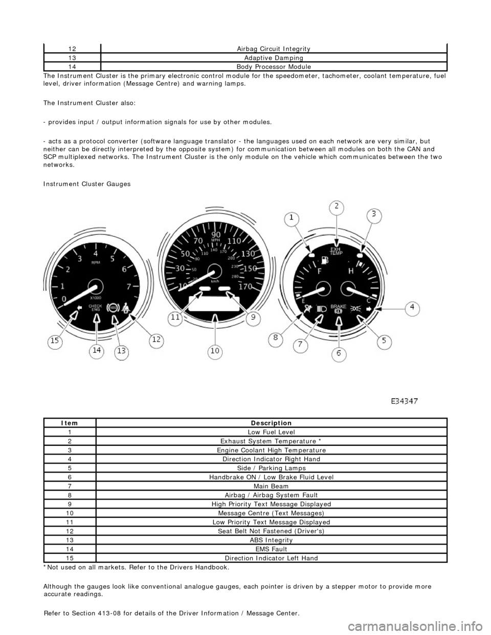
strument Cluster is the primary electronic control module for the speedomete
r, tachometer, coolant temperature, fuel
level, driver information (Message Centre) and warning lamps.
The Instrument Cluster also:
- provides input / output informatio n signals for use by other modules.
- acts as a protocol converter (software language translator - the languages used on each network are very similar, but
neither can be directly interp reted by the opposite system) for communication between all modules on both the CAN and
SCP multiplexed networks. The Instrument Cluster is the only module on the vehicle which communicates between the two
networks.
Instrument Cluster Gauges
*Not used on all markets. Refer to the Drivers Handbook.
Although the gauges look like conventional analogue gauges, each pointer is driven by a stepper motor to provide more
12Ai
rbag Circuit Integrity
13Adaptive Damping
14Body Processor
Module
It
em
De
scription
1Low Fu
el Level
2Exhaus
t System Temperature *
3E
ngine Coolant High Temperature
4Di
rection Indicator Right Hand
5Side
/ Parking Lamps
6Handbrake ON / Low
Bra
ke Fluid Level
7Main
Beam
8Ai
rbag / Airbag System Fault
9Hi
gh Priority Text
Message Displayed
10M
essage Centre (Text Messages)
11Low Pri
ority Text Message Displayed
12Se
at Belt Not Fa
stened (Driver's)
13ABS Integrity
14EMS Fault
15D
irection Indicator Left Hand
accu
rate readings.
Refer to Section 413-08 for details of the Driver Information / Message Center.
Page 1861 of 2490
Clock - Clock
Description and Operation
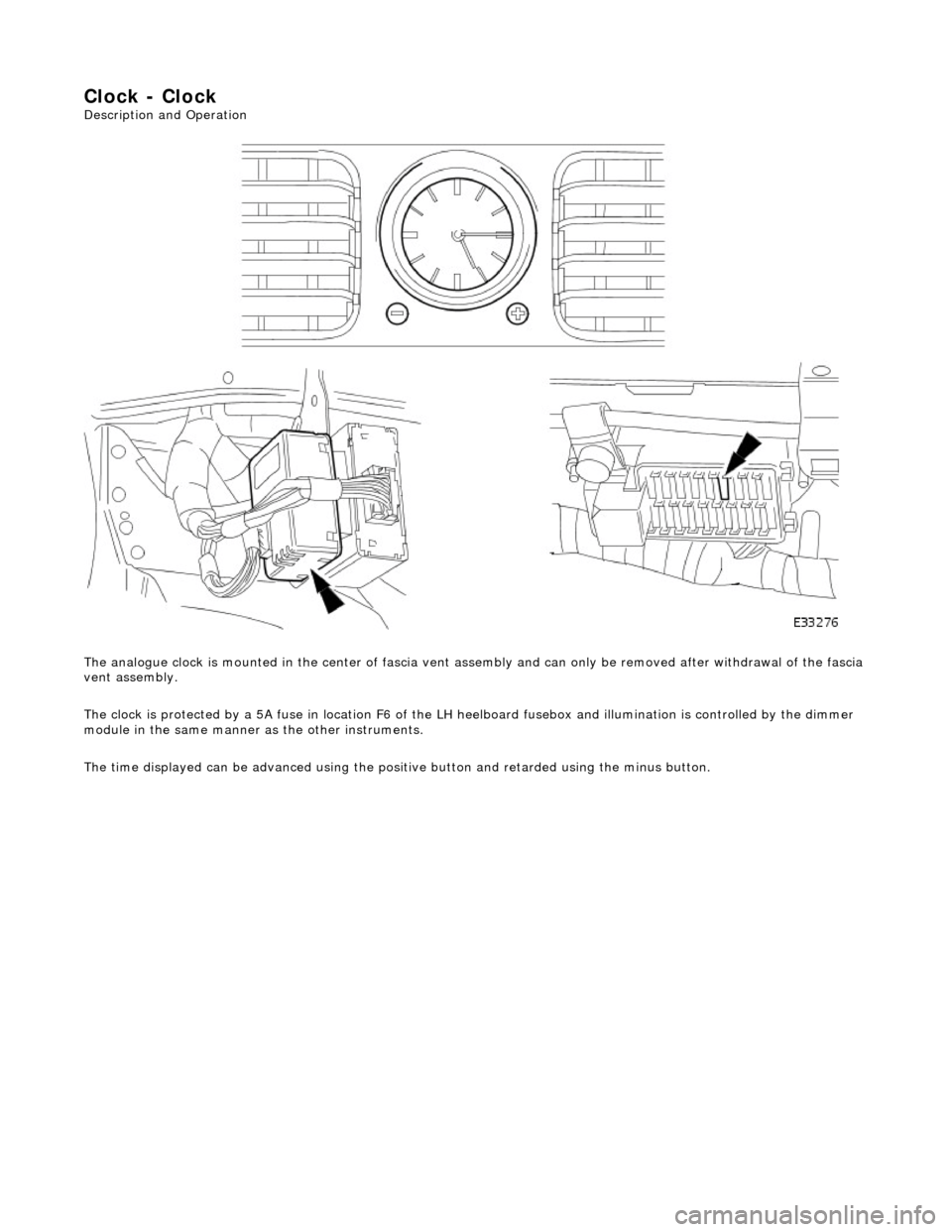
The analogue clock is mounted in the center of fascia vent assembly and can only be removed after withdrawal of the fascia
vent assembly.
The clock is protected by a 5A fuse in lo cation F6 of the LH heelboard fusebox and illumination is controlled by the dimmer
module in the same manner as the other instruments.
The time displayed can be advanced using the positive button and retarded using the minus button.
Page 1864 of 2490
Information and Message Center - Information and Message Center
Description and Operation
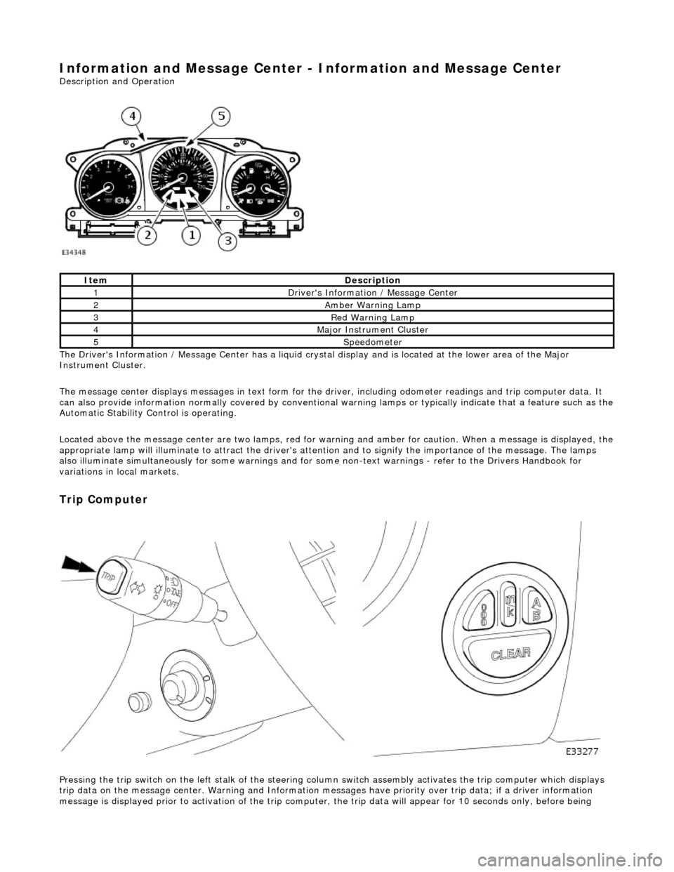
The Driver's Information / Message Center has a liquid crystal display and is located at the lower area of the Major
Instrument Cluster.
The message center displays messages in text form for the driver, including odometer readings an d trip computer data. It
can also provide information normally covered by conventional wa rning lamps or typically indicate that a feature such as the
Automatic Stability Control is operating.
Located above the message center are two lamps, red for warning and amber for caution. When a message is displayed, the
appropriate lamp will illuminate to attract the driver's attention and to signify the importance of the message. The lamps
also illuminate simultaneously for some warnings and for some non-text warnin gs - refer to the Drivers Handbook for
variations in local markets.
Trip Computer
Pressing the trip switch on the left stalk of the steering colu mn switch assembly activates the trip computer which displays
trip data on the message center. Warning and Information messages have priority ov er trip data; if a driver information
message is displayed prior to activation of the trip computer , the trip data will appear for 10 seconds only, before being
ItemDescription
1Driver's Information / Message Center
2Amber Warning Lamp
3Red Warning Lamp
4Major Instrument Cluster
5Speedometer