1998 ACURA INTEGRA rear
[x] Cancel search: rearPage 793 of 1680

Troubleshooting
ABS Indicator Does Not Go Off
JUMPERWIRE
ABS OO TNOL UMT 22P OO'{NECTOR
Wire side of temalo terminalg
A8S COI{TROL Ut{lT 12P OO I{ECTOR
JUMPEFWIRE
Wire side of femal€ terminala
|G2 IALK/YELI
- The ABS indicltor light doosnot go ofl aftor lhe engine is3tartod.- With the SCS sorvico connoctor connoct d l.oe page 19371,no DTC b indbat€d.
ChECK thE REAF DEFROSTERRELAY (7.5 A) fuse in the under-dash fuse/relay box, and reinstallthe fuso if it is OK.
Roplaco tho tusa and rocheck.
Chock for an opcn GND circuit:1. Connect the ABS control unit22P connector terminal No. 1to body ground with a jumper
2. Turn the ignition switch ON (ll).
. Ropair opon in tha wiro botwocntho ABS control unit and bodyground.' Ropair poo. ground {G701 }.
Check for an open in thc lG2 ci.-cuit:Measure the voltage botween theABS control unit 22P connectorterminal No. 11 and body ground.
Roprir opon in thc wira bdtwoentho REAR OEFROSTER RELAY17.5 Al fu$ end th. ABS controlunit.
ls th6re battery voltage?
Check the ABS contJol unit:Connect the ABS control unit 12Pconnector terminal No. 1 to bodyground with a jumper wire.
Chock for looao ABS control unhconncctoas, It nacas3aly, sub3ti-tuto a known-good ABS controlunit and r.check.
(To page 19-43)
19-42
Page 795 of 1680

- With the ignition switch ON(lll, the ABS indicator doesnot go off.- With the SCS s€.vice connec-tor connected lsee page 19-37), OTCS 11, 13, 15, 17 areindicated.
Check for a short to pow6r in thewheel sensor circuii:1. Disconnect the ABS controlu nit 22P connector.2. Start the engine.3, Measure the voltage betweenthe appropriate wheel sensor(+) circlit terminal and bodyground (see table).
Repair short to power in the {+)circuit wire between the ABScontrol unil and the approprialewheel sensor.
ls there 2 V or more?
Check for a short to body groundin th6 wheel sensor circuil:Check tor continuity between theappropriate wheel sensor (+) cir-cuit terminal and body ground(see table).. Ropair short lo body ground inthe {+) or {-l circuit wirebetween tho ABS contlol unitand th6 .ppropriate whe€l sen-
. Roplaco the .ppropliate wheelsensot.
ls there continuity?
Check for an open in the wheelsensor circuit:Check the resistance between theappropriate wheel sensor (+) and1-) circuit terminals (see table).
Ropair open in the {+) or (-} cir-cuit wire, or 3hort to the l+) cir-cuit wire in the l-l circuit wirebetween tho ABS control unitand th6 appropriate whgel 3en-
Replace th6 appropdate wh€elsensot.
ls the resistance OK?FronvRear: 450 - 2,050 O/20"c (68.F)
NOTE: lf you do not erase the DTC, the ABS indicator will not go off until vehicle speedexceeds 6 mph (10 km/h).
ABS CONTNOL UNIT 22P CONNECTOF
FLw {+l {GRN/ORN) FRw {+} (GRN/BLKI
oTcAppropriate Terminal
(+)Side( )side
11 (Right-front)No. 9: FRW (+)No. 8: FBW {-)
13 (Left'front)No.7: FLW (+)No.6: FLW 1-)
l5lBight-rear) iNo. 19:RRW (+!o. 20: RBW (-
17 (Left'r€af)17: RLW {+',1o. 18: RLW (-Wire side of lemale terminals
FLW (+) (GRN/ORN) FRW l+){GRN/BLK)
FLw l+l (GRN/ORNI FRW {-) {GRN}
FLW t-l(+l (GRN/BLKI
RL(-I {BLU/YELI
RLW l-) (GBY) RRW (+) (GRN/YEL)
Check for loose ABS control unitconnectors. lf necessary. substi-tute a known-good ABS controlunii and recheck.
RLW {+l (LT BLUI
RLw (+l {LT BLU}
-t(o
___r
l'!*
6l89l01t
1417t8t920
| ***-t
(()
Y
Troubleshooting
DTC 1 1, 13, 15, 17 : Wheel Sensor (open/short to body ground/short to power)
\
L
9-44
\
Page 796 of 1680

l
DTC121416, 18: Wheel Sensor {Electrical Noise/lntermittent lnterruptionl
- Wilh the ignition switch ONlll), the ABS indicator doesnot go off.- With the SCS service connec-tor connectcd (3e6 page 19-37), DTCa 12, 14, 16, or 18.reindicated.
Visually check for appropriatewheel sensor and pulser installation (see table).
Reinstall or replace th6 eppropri-ats wh6el sensor or puber.
Ch€ck lor a short to wire in thoone wheel s6nsor circuit:1. Disconnect the ABS controlunit 22P connector.2. Measu re the resistancebetween the appropriatewheel sensor (+) and (-) circuit terminals (see table).
Repair short to wire between theappropriate wheel sensor {+) and{-l circuits.ls there less than 450 0?
Check lor a short to .nother wirein lhe wheel sensor circuits:Check for continuity between theappropriate wheel sensor (+) circuit terminal and other wheelsensor (+i circuit terminals (see
table)-
R€psir short to wire between theappropriale wheol sensor andthe other wheel sensor.ls there continuity?
Eraso the DTC and test-drive thevehicle. lf ABS indicator comeson and same OTC is indiceted,reDlace the ABS control unil.
NOTE: ll the ABS indicator comes on for the reasons described below, the indicator should go
off when you test'drive the vehicle at speeds above 19 mph 130 km/h).. Only the drive wheels rotated. The vehicle spun. Electrical noise
DTCAppropriate Wheel Sensor
12Right - front
14Left front
Right - rear
18Left rear
DTCAppropriate Terminal
{+}Side(-)Side
12 (Right-front)No. 9: FRW (+)No.8: FRW (-)
'14 {Left-front)No. 7: FLW {+)No.6: FLW (-)'16 {Right-rear)No. 19: RRW 1+)No.20: RRW ( )
18 (Left-rear)No. 17: RLW (+)No. 18: RLW ( )
DTCAppropriateTerminalOther Terminal
12 (Right-tront)No.9: FBW (+)No. 7: FLW 1+)No. 19: RRW (+)No. 17: RLW (+)
14 (Left-front)No.7: FLW (+)No.9i FRW (+)No. 19: RRW (+)No. 17: RLW (+)
16 (Right-rear)No. 19r RRW {+)No.9: FRW (+)No. 7: FLW 1+)No.17: RLW (+)'18 (Left-rear)No. 17: RLW (+)No.9: FRW (+)No.7; FLW (+iNo. 19: RRW (+i
'
L
19-45
Page 797 of 1680

Troubleshooting
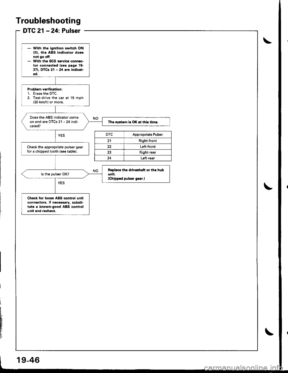
DTC 21 - 24: Pulser
- With tho ignition .whch ONlll), the A8s indic.tor do.!not go off.- With th. SCS..rvic. conn.c.tor connested l3.a pag€ 19-371, OTCa 21 - 24 116 indicrt-od.
Probl.m vorification:'1. Erase the DTC.2. Test-drive the car at 19 mph(30 km/h) or more.
Does the ABS indicator comeon and are oTCs 21 - 24 indi-cated?Th. .ytiam i. OK |t thi. tim.,
Check the appropriate pulser geartor a chipped tooth {see table).
Rcpl.c. ih. drlv..h.tt or th. hubunil.{Chippld pubd g..r.l
Chcck for loo.c ABS control unitconnectors. ll nace$ery, aubrti-tute . known-good ABS controlunit and racheck.
9-46
DTCAppropriate Pulger
21Right-front
22Left-front
Right-rear
Loft-rear
Page 801 of 1680

- while driving and dcprc$ingtho brakc oodrl, the ABS indi-catot com63 0n.- With the SCS service connac-tor connoctod lsoa page 19-371, DTCa 41 - a4 ar6 indicri-oo,
Do the brakos drag?
Check the installation of theappropriate wheel sensor instal-lation (see table).
. Th6 orobablo cau3o was thevehicle spun during cornaring..lf the problem occurs agcin,chock th6 modulator u.ing thoHonda PGM Tertar.
DTCAppropriate Wheel Sensor
41Right-front
42Left-front
4:]Right-rear
44Leii-rear
Troubleshooting
DTC 41 - 44: WheelLock
19-50
Page 813 of 1680

ABS Control Unit
RemovaUlnstallation
1. Remove the right quarter trim panel.
2. Disconnect the ABS control unit connectors.
3. Remove the ABS control unit.
Pulsers/Wheel Sensors
Inspection
/t
l\
I
Check the front and rear pulser for chipped or dam-
aged teeth.
Measure the air gap between tho wheel sensor and
pulser sllthe way around while rotating the pulser.
Standard: 0.4 - 1.0 mm (0.02 - 0.04 in)
NOTE: lf the gap exceeds 1.0 mm (0.04 in), the
probability is a distorted suspension arm which
should be reDlaced.
Front/R..1
L-TJ
.t-
t=
l-
Et-E_
Install the ABS control unit in the reverse order of
removal.
Start the engine, and check that the ABS indicator
goes off.
Test-drive the vehicle, and check that the ABS indi-
cator does not come on.
19-62
Page 815 of 1680

!
Body
Bumpers
Front Bumper Replacement ....................-..... 20-111
Rear Bumpar Replacemeni
Hatchback ................. 20-1/B
Sedan .................... ....20-111'Carpet
. Repfacemenl .,.,.,.,,..-....-.20-126
Consoles, Front and Rear
* Replacement ..................20-130
Dashboard
Component Removal/lnstallation ................ 20-133
Replacement Precautions ...........,................. 20-138
R€placement ....,.,...........20-139
Doors
Door Index Hatchback ................................... 20-2
Front Door Index Sedan .................,.,..,.,....,.. 20-18
Rear Door Index Sedan ........,.,........,.............. 20-30
Emblems
Installation .....................20-167
FenderwellTrim
+ Replacement., ................20.162
Fram€ Repair Chart .-..........20-170
Hatch
Replacoment .......,..........20-118
Adiustment .................... 20-150
Hatch Latch and Lock Cylinder
Replacement ..,.,..... ........ 20-158
Hstch Spoiler
Replacement ......... .......-.20.161
Hatch Weatherstrip/Trunk Lid Wsatherstrip
Replacement ..................20.163
Headliner
ReDlacement
Hatchbsck ,.,....,......,.. 20-98
Sedan .........................................................20-100
Hood
Replacsment ......... ......... 20.146
Adiustment ....................20-117
lnterior Trim
Reolacement
Hatchback ................. 20-91
Sedan .........................................................20-9,1
Mirrors
Power Mirror Reolacement ..........,................ 20-49
Mirrol Holder Removal ............................,..... 20.50
Mirror Holder Installation .............................. 20-50
Mirror Visor and Mirrot Covet
Replacement
Haichback ............20-51
Sedan .................................................... 20-51
Rearview Mirror Reolacement ..........-....-.-.... 20.52
Roof Molding Rep|acament ................................ 20.164
Door and Sid€ Moldings
Replacement .,..........,..... 20-165
Moonroot
lnd6x
Hatchback -................20-77
Sodan .........................................................20-8il
Opener and Latch
Replacement .......... ......,. 20-156
Opensr Cables
Replacamsnt .,.,...,.. ......., 20-154
Retainers and W€atherstrip
Replacement .................. 20-160
Seats
Front Seat Romoval ....................................... 20-103
Front Seat Replacement ...........................,.,.. 20-104
Front Soat Disassembly and Reassembly ...20-106
Torsion Bar ReDlacomant .....,...,......,.......,..,., 2O-1O7
Seat Eelt Switch Ha.ness Location ..,...,.,.,..,2O-1O7
Front Seat Cover Replacemont ..,....,..,..,.....,. 20-108
Rear Soat Roplscemont
Hatchback ................. 20.110
Sedan.........................................................20-112
R€al Seat Cover Replacomont ...................... 20-114
Seat Belts
Front Seat Beh Replacement
Hatchback..................20.117
Sedan20-r18
Rear S6at Bolt R€plac€ment
Hatchback .-......-.-......20-121
Sedan.......................-.-....-.-..........-.............20-122
fnspection ......-.-.,....-.-....20-121
Chifd Seat Anchor Plate ................................ 20-125
Side Sill Panol
Beplacom€nt .................. 20-166
Sub-frame ........................... 20.169
Trunk Lid
Replacement ......... ..,..,.,.20-151
Adiustmeni .................... 20-153
Trunk Lid Latch and Lock Cvlindot
Replac€ment ......... ......... 20-159
Trunk Trim
Replacement .,.,,.,........... 20-97
Windshield, Rear Window, Ouarter Glass
lndex
Hatchback ...........,,.20-53
!
S6dan ......................................................... 20.54
Page 824 of 1680

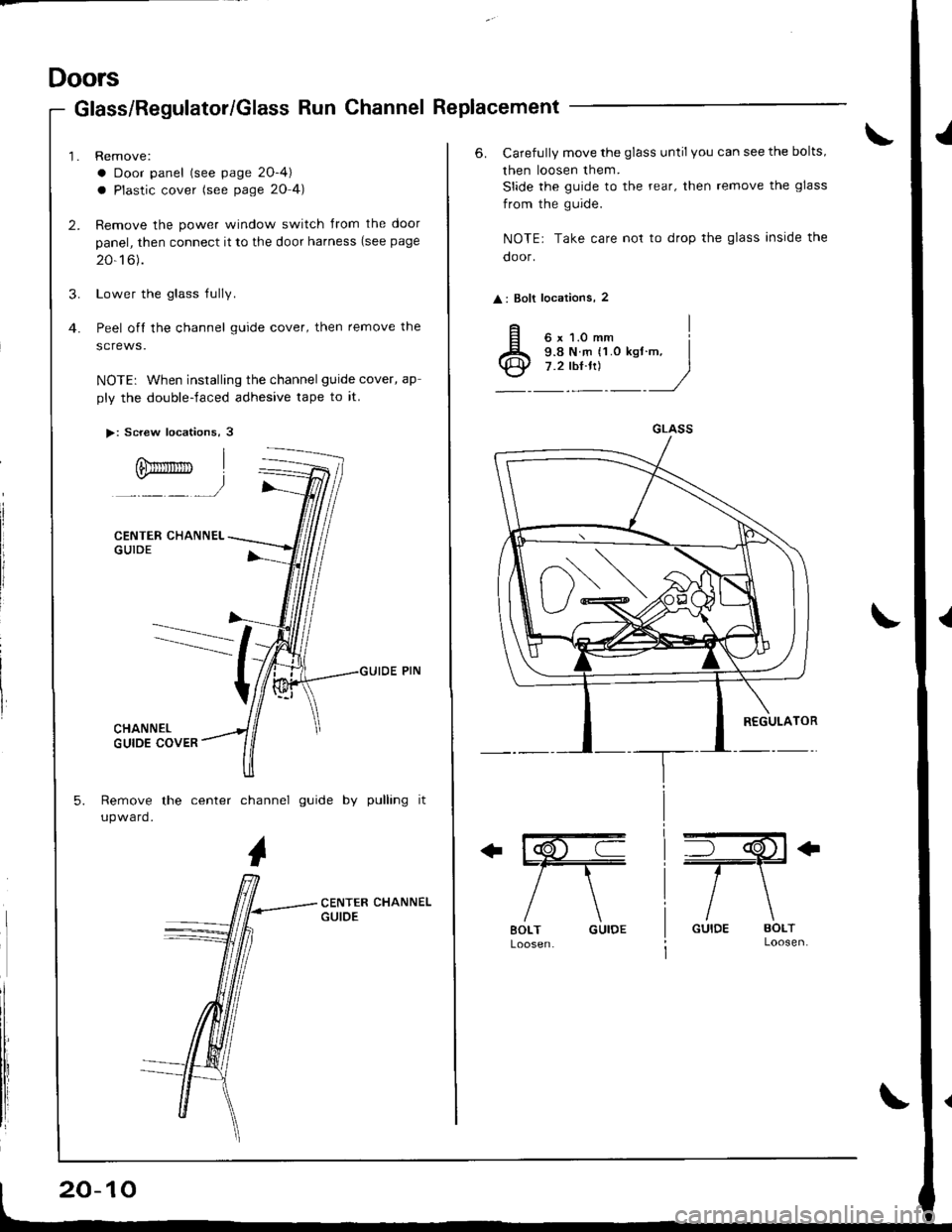
Doors
Glass/Regulator/Glass Run Channel Replacement
Remove:
a Door panel (see page 2O-4)
a Plastic cover (see page 20 4)
Remove the power window switch Jrom the door
panel, then connect it to the door harness (see page
20-16).
Lower the glass Iully.
Peel off the channel guide cover, then remove the
screws.
NOTE: When installing the channel guide cover, ap
ply the double-faced adhesive tape to it.
>: Screw locations, 3
CENTER CHANNELGUIDE
Remove the center channel guide by pulling it
upward.
Ofimnrrrn
20-10
6. Carefully move the glass until you can see the bolts,
then loosen them.
Slide the guide to the rear, then remove the glass
from the guide.
NOTE: Take care not to drop the glass inside the
door.
: Bolt locations, 2
ffi
/\
BOLT GUIDE
+il€+
/\
GUIDE BOLTLoosen.
GLASS