1998 ACURA INTEGRA brake master
[x] Cancel search: brake masterPage 35 of 1680

Lubrication Points
No. LUBRICAnON POINTSLUBRICANT
1 E^g,neAPI Service Grade: Use SJ "Energy Conserving" orSH "Energy Conserving ll" grade oil,The oil container may also display the API Certificationmark shown below. Make sure it savs "For GasolineEngines. "
SAE Viscositv: See chart below.
2TransmissionManualHonda Genuine MTF*1
AutomaticGenuine Honda Premium Formula AutomaticTransmission Fluid (ATF)*,
Brake line (lncludes Anti-lock brake line)Genuine Honda DOT3 Brake Fluid13
Clutch lineGenuine Honda DOT3 Brake Fluid*3
Power steering gearboxSteering grease P/N 08733 - 8070E
Release fork lManual transmission)Sup€r High Temp Urea Grease (P/N 08798 - 9002)
1
8
Throttle wire end (Dashboard lower oanel hole)Cruise control actuator wire end(Dashboard lower Danel hole)Silicone grease
o
10
11
14
Throttle cable end (Throttle link)Cruise control actuator cable end (Actuator link)Brake master cvlinder oushrodClutch master cylinder pushrod
Battery terminals
Fuel fill lid
Multi-purpose grease
to
17
18
Engin6 hood hinges and engine hood latchHatch hinges 8od latch or trunk hinges and latchDoor hjnges, upper and lowerDoor ooen detent
Honda White Lithium Grease
19Rear b.ake calipersSilicone grease
20Power steering systemGenuine Honda Power Steering Fluid-V or S*.
21Ai|' conditioning compressorRefrigerant oii ND-O|L8 {P/N38897 - PR7 - A01AH or38899-PR7-A01)(For Refrigerant: HFC-134a (R- 134a))
API SERVICE LABELAPI CERTIFICATION SEAL
Recommended engine oilEngin€ oil viscosity lorambrent lemperature ranges
r(For the details of lubrication points and type of lubricants to be applied, refer to the illustrated index and various work Dro-cedure (such as Assembly/Reassembly, Replacement, Overhaul, Installation. etc.) contained in each section,
*1: Always use Genuine Honda Manual Transmission Fluid (MTF). Using motor oil can cause stiffer shifting because itdoes not contain the proper addtuves.*2: Always use Genuine Honda Premium Formula Automatic Transmission Fluid (ATF). Using a non-Honda ATF can affectshift quality.*3: Always use Genuine Honda DOT 3 B.ake Fluid, Using a non-Honda brake fluid can cause corrosion and decrease thelife of the system.'4: Always use Genuine Honda Power Steering Fluid-V or S. Using any other type of power steering fluid or automatictransmission fluid can cause increase v,/ear and poor steering in cold weather.
L(
{
4-2
Page 361 of 1680
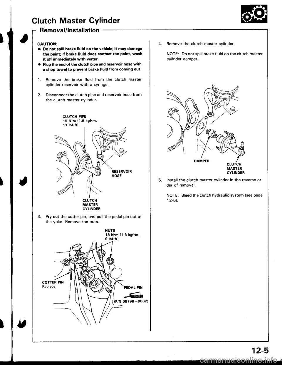
CAUTION:
a Do not 3pill brakefluid on the vehicle; it may damege
th€ paid; if brake fluid do63 contact th€ paint. wa3h
it otf immediately with water.
a Plug the end of the clutch pipe and reservoir hose with
a shop towel to prevent brake fluid from coming out.
1. Remove the brake fluid trom the clutch master
cylinder reservoir with a syringe,
2. Disconnect the clutch pipe and reservoir hose from
the clutch master cylinder.
Remove the clutch master cylinder.
NOTE: Do not spill braketluid ontheclutch master
cylinder damper.
CLUTCH PIPE15 N.m {1 .5 kgf'm,11 lbt.Ir)
5.
cLulcHMASTERCYLINDER
Install the clutch master cylinder in the reverse or-
der of removal.
NOTE: Bleed the clutch hydraulic system {see page
I z-ol.cturcHMASTERCYLINDER
Pry out the cotter pin, and pull the pedal pin out of
the yoke. Remove the nuts.
NUTS13 N.m {1.3 kgt.m,9 rbf.ftl
PEOAL PIN
-6rl(P/N 08798-90021
Clutch Master Cylinder
Removal/lnstallation
2-5
Page 362 of 1680
T
fi
;ill
Slave Cylinder
Removal/lnstallation
CAUTION:
a Do not spill brakelluid onthe vehicle; it may dameg€
the paint; if brake fluid does coniaqt the paint, wash
it otf immodiaioly wilh w8ter.
a Plug the end of the clutch pipe with a shop towel to
prevent brake fluid from coming out.
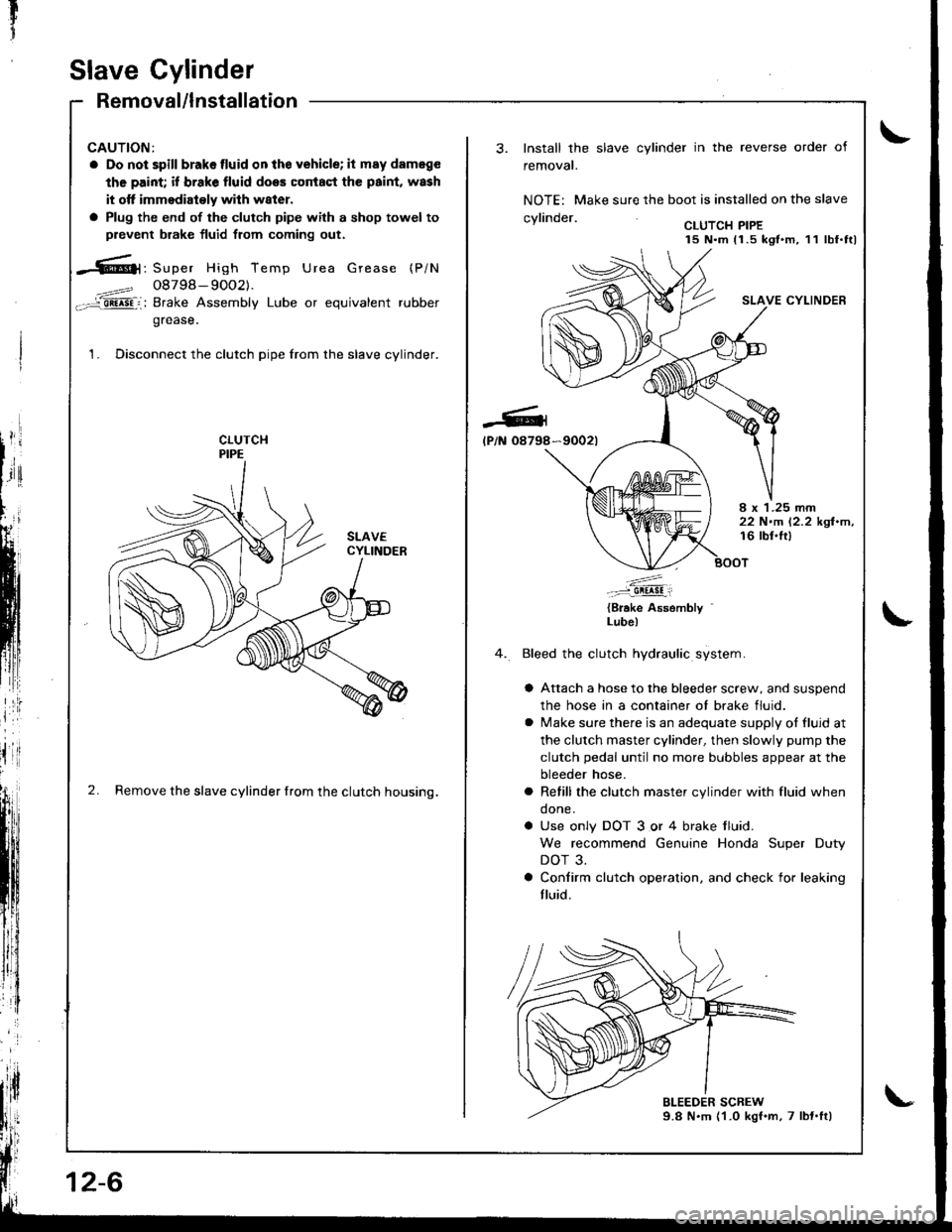
-6|1, Super High Temp Urea Grease (P/N
4==? 08798- 9OO2).-='aii^5Fi: Brake Assembly Lube or equivalent rubber
grease.
1. Disconnect the clutch pipe from the slave cylinder.
2. Remove the slave cylinder from the clutch housing.
12-6
-Gl
lP/N 08798
Install the slave cylinder in the reverse order of
removal.
NOTE: Make sure the boot is installed on the slave
.wlin.larCLUTCH PIPE15 N.m 11.5 kgt.m, 11 lbf.ttl
SLAVE CYLINDER
*9002t
I x 1.25 rnm22 N.m 12.2 kgl.m,16 lbl.lt)
.'....-..-:::-9!!!!!i
{Brake Assembly '
Lube)
Bleed the clutch hydraulic system.
a Attach a hose to the bleeder screw, and suspend
the hose in a container ot brake fluid.
a lvlake sure there is an adequate supply ot fluid at
the clutch master cylinder, then slowly pump the
clutch pedal until no more bubbles appear at the
bleeder hose.
a Refill the clutch master cylinder with fluid when
done.
a Use only DOT 3 or 4 brake tluid.
We recommend Genuine Honda Super Duty
DOT 3.
a Confirm clutch operation. and check for leaking
fluid.
Page 752 of 1680
Brakes
Special Tools ............. 19-2
Component Locations
Index ................ ...... 19-3
Inspection and Adiustment
Brake system Rubber Parts
and Brake Booster ....................... 19-4
Brake Pedal ............ 19-5
Parking Brake ........ 19-6
Bleeding ................. t9-7
Front Brake Pads
Inspection and Replacement .......... l9-B
Front Brake Disc
Disc Runout Inspection ................... 19-10
Disc Thickness and Parallelism
Inspection .......... 19-10
Front Brake Caliper
Disassembly/Reassembly ............... l9-1 l
Master Cylinder/Brake Booster
Removal/1nsta|lation ....................... 19-13
Master Cylinder Inspection ............. 19-14
Pushrod Clearance Adjustment ...... 19-14
Brake Booster Inspection,.............,, lg-15
Rear Brake Pads
Inspeetion and Replacement .......... l9-16
Rear Brake Disc
Disc Runout Inspection ................... 1 g-18
Disc Thickness and Parallelism
Inspection .......... t9-18
Rear Brake Caliper
Disassembly/Reassembly ............... l9-19
Brake Hoses/Lines
Inspection/Torque Specifications ... l9-20
Hose Replacement ...................... ..... 19-21
Parking Brake Gable
f nspection and Replacement ,......,.,19-22
Page 754 of 1680
Component Locations
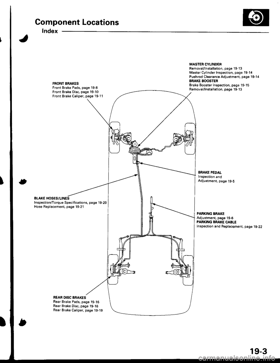
Index
FRONT BRAKESFront Brake Pads, page 19-8Front Brake Disc, page 19-10Front Brake Caliper, page 19-11
BLAKE HOSES/LINESInspection/Torque Specitications. page 19,20Hose Replacement, page 19-21
MASTER CYLINDEBR€moval/lnstallation, pag€ 19-'t3Mast€r Cylinder Inspection, page 19-14Pushrod Cl6aranc6 Adjustment, page 19-14BRAKE BOOSTERBrake Eoostor Inspoction, page 19-15Removal/lnstallation, pags'19-'13
BMKE PEDALlnspection andAdjustment, page 19-5
PARKING ERAKEAdjustment, page'19-6PARKING BRAKE CABLElnspoction and Roplacement, page 19-22
REAR DISC BRAKESRear Brake Pads, page 19-16Rear Brake Disc, page 19-18Rear Brake Caliper, page 19-19
19-3
Page 755 of 1680
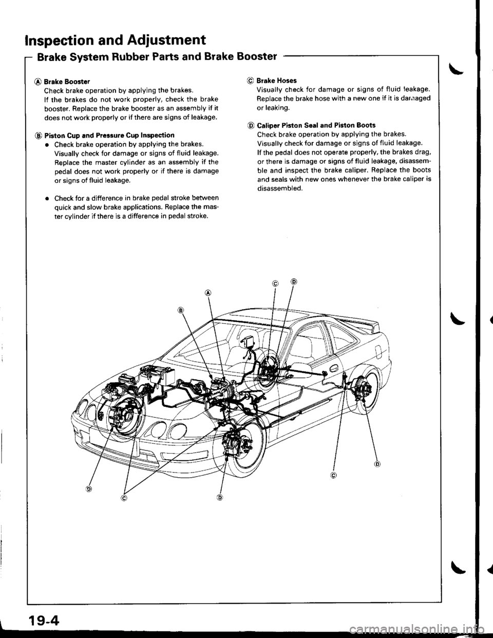
Inspection and Adiustment
Brake System Rubber Parts and Brake Booster
@ Brake Boost€r
Check brake operation by applying the brakes.
lf the brakes do not work properly, check the brake
booster. Replace the brake booster as an assembly if it
does not work properly or if there are signs of leakage
@ Piston cup and Pre3sure cup Inspection
. Check brake operation by applying the brakes.
Visually check for damage or signs of fluid leakage,
Replace the master cylinder as an assembly if the
pedal does not work properly or if there is damage
or signs of fluid leakage.
. Check for a difference in brake pedal stroke betlveen
quick and slow brake applications, Replace the mas-
ter cylinder if there is a difference in pedal stroke.
O Brake Hoses
Visually check for damage or signs of fluid leakage.
Replace the brake hose with a new one if it is darnaged
or leaking.
@ Caliper PBton Seal and Pkton Boots
Check brake operation by applying the brakes.
Visually check for damage or signs of fluid leakage.
lf the pedal does not operate properly, the brakes drag.
or there is damage or signs of fluid leakage, disassem-
ble and inspect the brake caliper. Replace the boots
and seals with new ones whenever the brake caliper is
disassembled.
19-4
Page 758 of 1680
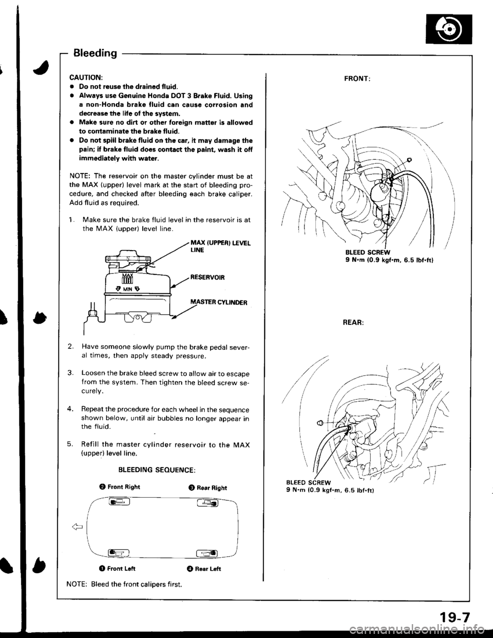
Bleeding
CAUTION:
. Oo not reuse the drsined fluid,
. Always use Genuine Honda DOT 3 Brake Fluid. Using
a non-Honda brake fluid can cause corrosion and
decrease the lile of the system,
a Make sure no dirt or other foreign matt€t is allowed
to contaminate the brske fluid.
. Do not spill brake fluid on tho car, it may damage the
pain; if brake fluid does contact the paint, wash it off
immediately with water.
NOTE: The reservoir on the master cylinder must be at
the MAX (upper) level mark at the start of bleeding pro-
cedure, and checked after bleeding each brake caliper.
Add fluid as required.
1. Make sure the brake fluid level in the reservoir is at
the MAX (upper) level line.
MAX (UPPER) I.IVELLINE
CYIINDER
Have someone slowly pump the brake pedal sever-al times, then apply steady pressure.
Loosen the brake bleed screw to allow air to escapefrom the system. Then tighten the bleed screw se-curely.
Repeat the procedure for each wheel in the sequenceshown below, until atr bubbles no longer appear inthe fluid.
Refill the master cylinder reservoir to the MAX(upperl level line,
BLEEDING SEOUENCE:
e, Front RightO Roa. Right
O Front Left Gt Raar L€ft
Bleed the front calipers first.NOTE:
19-7
FRONT:
REAR:
9 N.m {0.9 kgI'm,6.5 lbt.fr)
/
lc
,,
l,
Page 764 of 1680
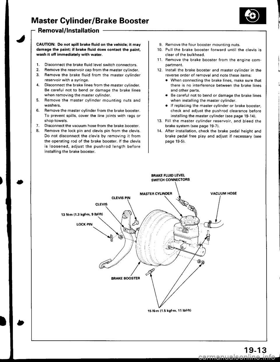
Master Cylinder/Brake Booster
I'RemovaUlnstallation
CAUTION: Do not spill brake tluid on the vehicle; it may
damage the paint; if brake fluid does contact the paint,
wash it oft immediatoly with water.
l. Disconnect the brake fluid level switch connectors.
2. Remove the reservoir cap from the master cylinder.
3. Remove the brake fluid from the master cvlinder
reservoir with a syringe.
4. Disconnect the brake lines from the master cylinder.
Be careful not to bend or damage the brake lines
when removing the master cylinder.
5. Remove the master cylinder mounting nuts and
washers.
6. Remove the master cylinder from the brake booster.
To prevent spills, cover the line joints with rags or
shoD towels.
7. Disconnect the vacuum hose from the brake booster.
8. Remove the lock pin and clevis pin from the clevis.
Do not disconnect the clevis by removing it from
the operating rod of the brake booster. lf the clevis
is loosened, adjust the pushrod length before
installing the brake booster.
13 N.m (1.3 kgf'm, 9 lbl'ft)
LOCX PIN
9. Remove the four booster mounting nuts.
10. Pull the brake booster forward until the clevis is
clear of the bulkhead.
11. Remove the brake booster from the enqine com-
panmenL
12, Install the brake booster and master cylinder in the
reverse order of removal and note these items:
. When connecting the brake lines, make sure that
there is no interference between the brake lines
and other parts.
. Be careful not to bend or damage the brake lines
when installing the master cylinder.
. lf replacing the master cylinder or brake booster,
check and adiust the DUshrod clearance before
installing the master cylinder (see page 19-14).
13. Fill the master cylinder reservoir, and bleed the
brake system (see page 19-7).'14. After installation, check the brake pedal height and
brake pedal free play and adjust if necessary (see
page 19-5).
BRAKE FLUID LEVEL
SW]TCH CONNECTORS
MASTER CYLINOERVACUUM HOSE
J
15 N.m t1.5 kgl'm, 11 lbf'ft)