1998 ACURA INTEGRA brake master
[x] Cancel search: brake masterPage 765 of 1680

Master Cylinder/Brake Booster
Master Cylinder InspectionPushrod Clearance Adjustment
NOTE: Master cylinder pushrod'to piston clearance must
be checked and adjustments made, if necessary, before
installing master cylinder.
1. Set the special tool on the master cylinder body;
push in the center shaft until the top of it contacts the
end of the socondary piston by turning the adjusting
nut.PUS'IROD ADJUSTTTiENT GAUGE07JAG - SDiOl(xl
SECOITDARYPISTON
CEl{IERSHAFT
MASTER CYLINDER
Without disturbing the center shaft's position,
the soecial tool upside down on the booster.
3. Install the master cylinder nuts and tighten to the
sDecified toroue.
4. Connect the booster inline with a vacuum gauge 0 -
101 kPa {0 - 760 mmHg, 30 in.Hg) to the booster's
engine vacuum supply, and maintain an engine
speed that will deliver 66 kPa (500 mmHg, 20 in.Hg)
vacuum.
5. With a feeler gauge, measure the clearance between
the gauge body and the adjusting nut as shown.
Clsarance: 0 - 0,i[ mm (0 - 0.02 inl
VACUUM GAUGElCommelcially availabl€|0 - 101 kPal0 - 760 mm H9,30 in.Hgl
AINUSTING NUT
BRAKEBOOSTEB
MAS'ER CYLINDER NUT15 N.m ll.5 kgf.m. 11 lbl.ftl
CAUTION:
. Do not spill blake fluid on the vohicle; it may damago
th6 paint; if brake fluid does contast ths paint, wash
it off immsdiately with water.
. Before reassembling. chock that all parts are tree of
dust and othor toreign particlgs,
. Do not trv to dissssemblo the master cylinder
assembly. Replace the mast€r cylinder assembly
with s new part if nocossary.
. Make sure no dirt or othor toroign matter is allowed
to contaminate th€ brako fluid.
RESERVOIR SEALCheck for damage and
deterioration.
ROD SEALCheck for damageand deterioration.
AIIUSNNG NUT
19-14
FEELER GAUGE
Page 766 of 1680

1.
8.
NOTE: lf the clearance between the gauge body
and adjusting nut is 0.4 mm (0.02 in), the pushrod-
to-piston clearance is 0 mm. However, if the clear-
ance between the gauge body and adjusting nut is
0 mm, the pushrod-to-piston clearance is 0.4 mm(0.02 in) or more. Therefore it must be adjusted and
rechecked.
lf clearance is incorrect, loosen the star locknut and
turn the adjuster in or out to adjust.
NOTE:
. Adjust the clearance while the specified vacuum
is applied to the booster.
. Hold the clevis while adjusting.
Tighten the star Iocknut securely.
Remove the special tool.
0 - o.il mm l0 - 0.02 inl
Brake Booster Inspection
Functions Tgst
1. With the engine stopped, depress the brake pedal
several times to deplete the vacuum reservoir, then
depress the pedal hard and hold it for 15 seconds. ll
the pedal sinks, either the master cylinder is
bypassing internally; or the brake system (master
cylinder, lines, modulator proportioning valve, orcaliper) are leaking.
Start the engine with the pedal depressed. lf thepedal sinks slightly, the vacuum booster is operat-
ing normally. lf the pedal height does not vary, the
booster or check valve is faulty.
With the engine running, depress the brake pedal
lightly. Apply just enough pressure to hold back
automatic transmission creep, lf the brake pedal
sinks more than 25 mm (1.0 in.) in three minutes,
the master cylinder is faulty. A slight change inpedal height when the A,,/C compressor cycles on
and off is normal. (The A/C compressor load
changes the vacuum available to the booster.)
Leak Test
1. Depress the brake pedal with the engine running,
then stop the engine. lf the pedal height does not
vary while depressed for 30 seconds, the vacuum
booster is OK. lf the pedal rises, the booster is
fau lty.
2. With the engine stopped, depress the brake pedal
several times using normal pressure. When thepedal is first depressed, it should be low. On con-
secutive applications, the pedal height should grad-
ually rise. lf the pedal position does not vary, check
the booster check valve.
Boostor Ch€ck Valve T6st
1. Disconnect the brake booster vacuum hose at the
booster,
Start the engine and let it idle. There should be vac-
uum available. It no vacuum is available. the check
valve is not working properly. Replace the brake
booster vacuum hose and check valve, and retest.
VACUUM HOSE(Check valve built-in)
STAR LOCKNUT22 t{.m12.2 ksl.m, 16lbf.ftl
cLEVtS
ADJUSTER
ADJUSTMENT GAUGE07JAG - SD40t00
9. Adjust the pushrod length as shown if the booster
is removed.
1161 0.5 mm14.61 0.02 inl
PUSHRODLOCKNUT15 N m 11.5 kgf m, 11 lbf'ftl
10. Instali the master cylinder.
Page 771 of 1680

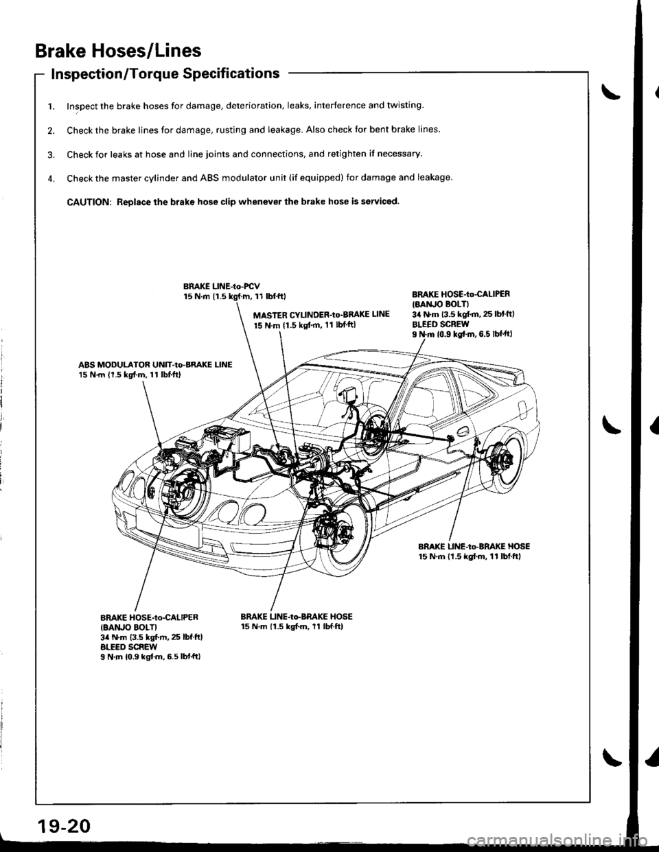
Brake Hoses/Lines
Inspection/Torque Specif icationsInspecuon/ | orque Dpecl carlon
1. Inspect the brake hoses for damage, deterioration, leaks, interference and twisting
2. Check the brake lines for damage, rusting and leakage. Also check tor bent brake lines.
3. Check ior leaks at hose and line joints and connections, and retighten if necessary.
4. Check the master cylinder and ABS modulator unit (if equipped) for damage and leakage.
CAUTION: Replace the braks hose clip whenever the brake hose is serviced.
15 N.m 11.511 tbl.f0
MASTER CYLINDER'Io'BBAKE UNE
15 N.m {1.5 kgt'm, 11 lbf ft}
BnAKE HOSE-Io-CALIPER
IMNJO BOLTI3a N'm 13.5 kgf.m. 25 lbl ft)
BLEED SCREWI N.m 10.9 ks{.m,6.5 lbf.ftl
ABS MODULATOR UNIT-Io-BRAKE LINE15 N.m (1.5 kg{.m, 11 lbtftl
BRAKE LINE-Io-BRAKE HOSE15 N'm lt.5 kgf.m, 11 lbf.ftl
BnAKE HOSE-Io-CALIPER
IBAruO BOLTI3il N.m (3.5 kgt m, 25 lbf.ft)ALEED SCREWI N'm 10.9 kgtm,6.5lbf.ftl
BRAKE LINE-Io-BRAKE HOSE15 N.m 11.5 kgfm, 11 lbf.ftl
BMKE LINE-Io-FCV
l
It
I
i
i
i
Page 779 of 1680

Anti-lock Brake System (ABS)
Features/Construction (cont'd)
ABS Modulatol
The ABS modulator consists of the inlet solenoid valve, outlet solenoid valve, reservoir, pump, pump motor and the
damping chamber.
The modulator reduces the caliper fluid pressure directly. lt is a circulating-type modulator because the brake fiuid circulates
through the caliper, reservoir and the master cylinder.
The hydraulic control has three modes: pressure reduction, pressure retaining and pressure intensiiying
The hvdraulic circuit is the independent four channel-type, one channel tor each wheel'
L-__
RF LR
Pressure intensifying mode: Inlet valve open, outlet valve closed
Master cvlinder fluid is pumped out to the caliper.
Inlet valve closed, outlet valve closed
Caliper fluid is retained by the inlet valve and outlet valve.
lnlet valve closed, outlet valve open
Caliper fluid flows through the outlet valve to the reservolr'
When starting the pressure reduction mode, the pump motor is ON.
When stopping ABS operation, the pump motor is OFF.
The reservoir fluid is pumped out by the pump, through the damping chamber, to the master
cylinder.
\
Pressure retaining mode:
Pressure reduction mode:
Motor operation mode:
sott orD vALvE
@@-@@
TASIEF CYLI'OEF
19-24
Page 787 of 1680

Troubleshooting Precautions
Kickback
L The motor operates when the ABS is functioning, and the fluid in the reservoir is forced out to the master cylinder,
causing kickback at the brake pedal.
Pump Motol
1. The pump motor operates when the ABS is functioning.
2. The ABS control unit checks the pump motor operation during initial diagnosis and when the vehicle is started. You
mav hear the motor operate at this time, but it is normal
Brake Fluid Replacement/Air Bleeding'1. Brake fluid replacement and air bleeding procedures are the same as vehicles without ABS. To ease bleeding, start
with the front wheels.
Troubleshooting
1. The troubleshooting flowcharts procedures assume that the cause of the problem is still present and the ABS indica-
tor is still on. Following the flowchart when the ABS indicator does not come on can result in incorrect diagnosis.
2. Ouestion the customer about the conditions when the problem occurred, and try to reproduce the same conditions
for troubleshooting.
Find out when the ABS indjcator came on. such as during initial diagnosis. during ABS control, after ABS control,
when vehicle speed was at a certain speed, etc.
3, When the ABS indicator does not come on during the test-drive, but troubleshooting is performed based on the DTC,
check for loose connectors, poor contact at the terminals, etc. before you start troubleshooting'
4. After troubleshooting, erase the DTC and test-drive the vehicle. Be sure the ABS indicator does not come on.
5. The connector illustrations show the female terminals with a single outline and the male terminals with a double outline.
Page 812 of 1680

Modulator Unit
Removal/lnstallation
CAUTION:
. Do not spill brake fluid on lhe vehicle; it may damage the paint; il brake fluid does contact the paint, wash it offimmediately with water.
. Tak€ care notto damage or delorm the brake lines during removal and installation.. To provont the brake fluid ftom flowing, plug and cover the hos€ ends and ioints with a shop towel or equiyalent material.
Removal
1. Disconnect the modulator unit and DUmD motor connectors.
2. Disconnect the brake lines, then remove the modulator unit.
Installation
1. lnstall the modulator unit, then connect the brake lines. Tighten the flare nuts to 15 N.m (1.5 kgf.m, 11 lbf.ft).2. Connect the modulator unit and pump motor connectors.
3. Bleed the brake system, starting with the front wheels.
4. Start the engine, and check that the ABS indicator goes off.
5. Test-drive the vehicle, and check that the ABS indicator does not come on.
From master cylinder
from master cylinderprimary side
PUMP MOTOB CONNECTOR
MOUNT
UNlT
MODULATOR UNIT CONNECTOR
toright front
8 mm EOLT22 N.m {2.2 kg[.m, 16 lbl.ftl
6 mm NUT9.8 N.m 11.0 ks{.m,7.2lbtftl
9-6
Page 1405 of 1680

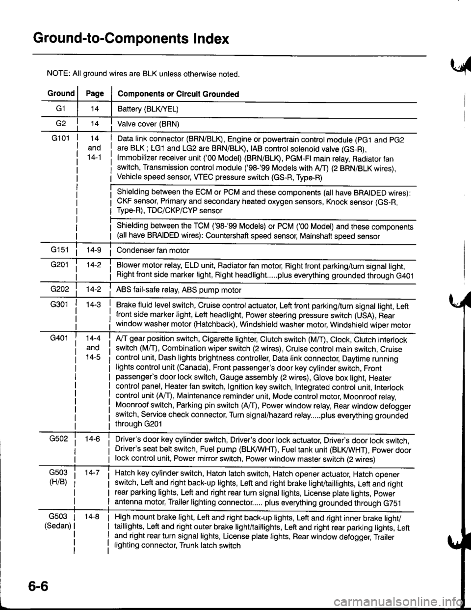
Ground-to-Components I ndex
NOTE: All ground wires are BLK unless otherwise noted.
GroundPageComponents or Circuit Grounded
Battery (BLIVYEL)
--t'I Valve cover (BRN)
G101t.+
and
14-1
Daia link connector (BRN/BLK), Engine or powertrain controt module (pct and pG2
are BLK; LG1 and LG2 are BRN/BLR, IAB controt solenoid valve (GS-B),
lmmobilizer receiver unit ('00 Model) (BRN/BLR, PGM-Ft main retay, Radiator fan
switch, Transmission control module ('98.�99 Models with MD (2 BRN/BLK wires),
Vehicle speed sensor, WEC pressure switch (GS-R, Type-R)
Shielding between the ECM or PCM and these components (all have BRAIDED wires):
CKF sensor, Primary and secondary heated oxygen sensors, Knock sensor (GS-R,
Type-R), TDC/CKP/CYP sensor
Shielding between the TCM ('98-'99 Models) or PCM ('00 Model) and these components(all have BRAIDED wires): Countershaft speed sensor, Mainshaft speed sensor
G1s1 ii Condenser fan motor
Brake fluid level switch, Cruise control actuator, Left front parking/turn signal light, Left
front side marker light, Left headlight, Power steering pressure switch (USA), Rear
window washer motor (Hatchback), Windshield washer motor, Windshield wiper motor
14-3
Blower motor relay, ELD unit, Badiator fan motor, Right front parking/turn signal light,
Right front side marker light, Right headlight.....plus everything grounded through G401
ABS fail-safe relay, ABS pump motor
G40114-4
ano
l4-c
A,/T gear position switch, Cigarette lighter, Clutch switch (M,/T), Ctock, Ctutch interlock
switch (MfD, Combination wiper switch (2 wires), Cruise control main switch, Cruise
control unit, Dash lights brightness controller, Data link connector, Daytime running
lights control unit (Canada), Front passenger's door key cylinder switch, Frontpassenger's door lock switch, Gauge assembly (2 wires), Glove box light, Heater
control panel, Heater tan switch, lgnition key switch, Integrated control unit, Interlock
control unit (AfI), Maintenance reminder unit, Mode control motor, Moonroof relay,
Moonroof switch, Parking pin switch (AfD, Power window relay, Rear window defogger
switch, Service check connector, Turn signal/hazard relay.....plus everything grounded
throuoh G201
Driver's door key cylinder switch, Driver's door lock actuator, Drivels door lock switch,Driver's seat belt switch, Fuel pump (BLI(/WHT), Fuel tank unit (BLI(/WHT), power doorlock control unit, Power mirror switch, Power window master switch (2 wires)
Hatch key cylinder switch, Hatch latch switch, Hatch opener actuator, Hatch ooener
switch, Left and right back-up lights, Left and right brake light/taillights, Lett and right
rear parking lights, Left and right rear turn signal lights, License plate lights, power
antenna motor, Trailer lighting connector..... plus everything grounded through G751
6-6
'14-8G503
(Sedan)
High mount brake light, Left and right back-up lights, Lett and right inner brake tighv
taillights, Left and right outer brake light/taittights, Left and right rear parking tights, Leftand right rear turn signal lights, License plate lights, Rear window detogger, Trailer
lighting connector, Trunk latch switch
Page 1654 of 1680

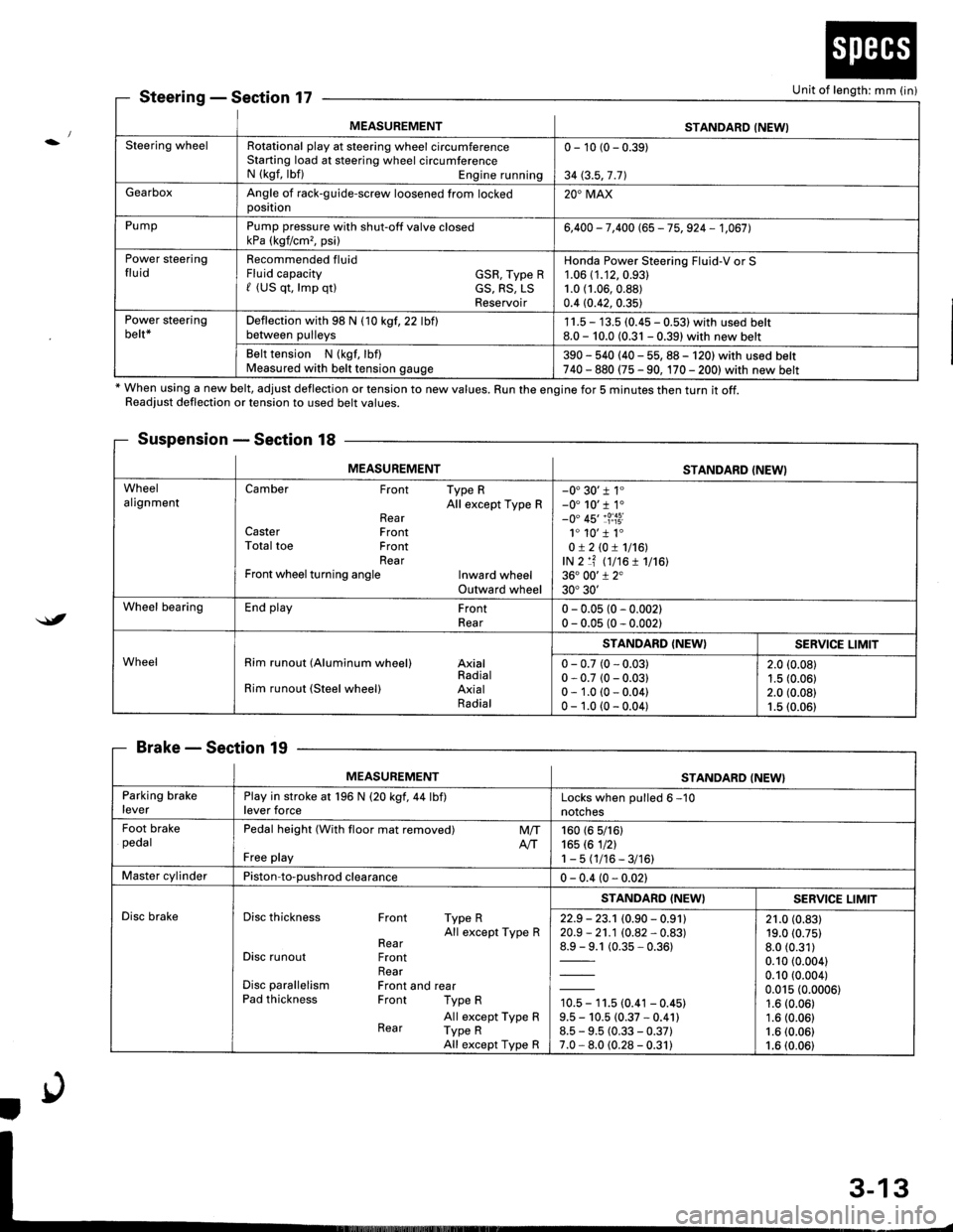
MEASUREMENTSTANDARD (NEWI
Steering wheelRotational play at steering wheel circumferenceStarting load at steering wheel circumferenceN (kgf, lbf) Engine running
0 - 10 (0 - 0.39)
34 (3.5,7 .71
GearboxAngle of rack-guide-screw loosened from lockedoosition20'MAX
PumpPump pressure with shut-off valve closedkPa (kgf/cm,, psi)6,400 - 7,400 (65 - 75, 924 - 1,067],
Power steeringfluidRecommended fluidFluid capacity GSR, Type Rf (US qt, lmp qtl cS, RS, LSReservoir
Honda Power Steering Fluid-V or S1.06 (1.12,0.93)
1.0 (1.06,0.88)
0.4 (0.42, 0.35)
Power steeringbelt*Deflection with 98 N (10 kgf,22 lbflbetween pulleys1 1.5 - 13.5 (0.45 - 0.531 with used belt8.0 - 10.0 (0.31 - 0.39) with new belt
Belt tension N (kgf, lbf)Measured with belt tension gauge390 - 540 (40 - 55, 88 - 120) with used belt740 - 880 (75 - 90, 170 - 2001with new belt
SteeringSection 17
* When using a new belt, adjust deflection or tension to new values. Run the engine for 5 minutes then turn it off.Readiust deflection or tension to used belt values.
Suspension - Section 18
BrakeSection 19
Unit of length: mm (in)
$t
MEASUREMENTSTANDARD (NEWI
WheelalignmentCamber Front Type RAll except Type RRearCaster FrontTotal toe FrontRearFront wheel turning angle Inward wheelOutward wheel
-0'30'r 1"-0' 10'r 1.-0" 45'�1?:i3i1. 10'�1 1.0!210!1116!,lN 2 lf (t7t6 1 1716136. 00'1 2"30'30'
Wheel bearingEnd play FrontRear0 - 0.05 (0 - 0.002)0 - 0.05 (0 - 0.002)
WheelRim runout (Aluminum wheel) AxialRadialRim runout (Steel wheel) AxialRadial
STANDARD (NEW}SERVICE LIMIT
0 - 0.7 (0 - 0.03)0 - 0.7 (0 - 0.03)0 - 1.0 (0 - 0.04)0 - 1.0 (0 - 0.04)
2.0 (0.08)
1.5 (0.06)2.0 (0.08)1.5 (0.06)
MEASUREMENTSTANDARD (NEW}
Parking brakeleverPlay in stroke at 196 N (20 kgf,44 lbf)lever forceLocks when oulled 6 -10
notches
Foot brakepedalPedal height (With floor mat removed)
Free play
M/TAtT160 (6 5/161165 rc 1nl1-5(1/16-3/16)
Master cylinderPiston-to-oushrod clearance0 - 0.4 (0 - 0.021
Disc brakeDisc thickness Front Type RAll except Type RRearDisc runout FrontRearDisc parallelism Front and rearPad thickness Front Type R
All except Type RRear Type RAll except Type R
STANDARD (NEWISERV]CE LIMIT
22.9 - 23.1 (0.90 - 0.91120.9 - 21.1 (0.82 - 0.83)
1= t (0.35-0.361
10.5 - 11.5 (0.41 - 0.45)9.5 - 10.5 (0.37 * 0.41)8.5 - 9.5 (0.33 - 0.37)7.0 - 8.0 (0.28 - 0.31)
21.0 (0.83)19.0 (0.75)
8.0 (0.31)
0.10 (0.004)
0.10 (0.004)
0.015 (0.0006)1.6 (0.06)
1.6 (0.06)1.6 (0.06)
1.6 (0.06)