1998 ACURA INTEGRA spark plug
[x] Cancel search: spark plugPage 66 of 1680

Valve Seals
Replacement (cylinder head removal not required)
The procedure shown below applies when using the in-
car valve spring compressor (Snap-on YA8845 with
Y AAA45-2A 1 /8" attachment).
!@@ When using this tool, as with any tool,
always use approved eye protection. Using the
fight tool tor each job helps increase productivity
while safeguarding tools, equipment and ihe user.
Turn the crankshaft so that the No. 1 and the No. 4pistons are at top dead center (TDC).
Remove the cylinder head cover.
Remove the distributor.
Loosen and disconnect the timinq belt from the
camshaft oullevs.
5. Remove the camshaft holder bolts, then remove the
camshaft holders, the camshafts and rocker arms.
Intake Valve Seals
6. Using the 6 mm bolts supplied with the tool, mount
the two uprights to the cylinder head at the end
camshaft holders. The uprights fit as shown.
7. Insert the cross shaft through the bottom hole of
the two uprights.
8.
9.
10.
Select the 7/8 in. diameter long compressor attach-
ment and fasten the attachment to the No. 4 hole of
the lever arm with the speed pin supplied.
Position the piston at TDC and insen an air adaptor
into the spark plug hole. Pump air into the cylinder
to keep the valve closed while compressing springs
and removing the valve keepers.
Position the lever arm under the cross shaft so the
lever is perpendicular to the shaft and the compres-
sor attachment rests on top of the retainer for the
spring being compressed. Use the rear position slot
on the lever as shown.
NOTE: Put shop towels over the oil passages toprevent the valve keepers from falling into the cylin-
der head.
OIL PASSAGE
OIL PASSAGES
(cont'd),'.itil
i,
'6-b-'
Page 282 of 1680

PGM-FI System
Random Misfire
1T0-500 1 a nd Fo-30ittrrousFF0304-lThB scan tool indicates Diagnostic Trouble Code {DTC) P0300 and some of
P0301 - P0304: Random misfire.
Doscription
Misfir; detection is accomplished by monitoring the crankshaft speed with the crankshaft speed fluciuation sensor which
is attached to the crankshsft.
lf misfiring strong enough to damage the catalyst is detected, the MIL will blink during iho time of its occurrence, and DTC
p0300 and some of DTCS p0301 through P0304 will be stor€d. Then, after misfire has ceased, the MIL will come on.
lf misfiring that increases emissions is detected during two consecutive driving cycles, the MIL will come on, and DTC
PO3O0 and some ot DTCS P0301 through P0304 will be stored
NOTE: lJ some of the DTCS listed below are stored at the same time as a misfire DTC, troubleshoot those DTCS first. then
troubleshoot the misfire DTC.
P0171, P0172: Fuel metering
P0505: ldle Control SYstem
P1361, P1362: TDC sensor
P1381. P1382: CYP sensor
P1508: IAC valve
Possible Cause
. Fuel pump insufficient fuel pressure. amount of flow
. Fuel line clogging, blockage, leakage
. Fuel {ilter clogging
a Fuel pressure regulator stuck open
. Distributormallunction
o lgnition coil wire open, leakage
. lgnition control module malfunction
. Valves carbon deposit
a Compression low
. IAC valve malfunction
. Fast idle thermo valve malfunction
o Fuel does not meet Owner's Manual spec., lackotfu€l
. VTEC system malfunction
Troubleshooting
By test-driving, determine the conditions during which misfire occurs. Depending on these conditions, test in the order
described in the table below.
Fuel
pressure
Distributor
and lgnition
wires
tcMIAC ValveValve
Clearance
wEc
System
11118section 23section 231 1- 100section 6section 6
Only low rpm and
loao@o@@
Only acceleratingo@o
Only high rpm and
loado@@@o
Not specificationo@@@@
NOTE: lf misfire doesn't recur, some possible causes arefuel that doesn't meet owner's manual spec, lackoffuel, carbon
deposits on spark plug, etc.
11-78
Page 283 of 1680

Misfire Detected in One Cylinder
I P0301 The scan tool indicates Diagnostic Trouble Code (DTC) PO3O1:Cylinder 1 misfire detected.
[F03021 1;," """n tool indicares Diagnostic Troubte Code (DTC) pO3O2: Cylinder2 misfire detected.
P0303 | ths sssn tool indicates Diagnostic Trouble Code (DTC) PO3O3: Cylinder3 misfire detected.
i P0304 | tne scan tool indicates Diagnostic Trouble code {DTC} PO3O4: Cylinder 4 misfire detected.
Doscription
Misfire detection is accomplished by monitoring the crsnkshaft speed with the crankshaft speed fluctuation sensor whichis attached to the crankshaft.
lf misfiring strong enough to damage the catalyst is detected, the MIL will blink during the time of its occurrence, and DTCP0301, P0302, P0303 or P0304 will be stored. Then, after the m;sfire has ceased, the MIL witt come on.lf misfiring that increases emissions is detected during two consecutive driving cycles, the MIL will come on, and DTCP0301, P0302, P0303 or P0304 will be stored.
NOTE: lf some of the DTCS listed below are stored at the same time as a misfire DTC, troubleshoot those DTCS first, thentroubleshoot the misfi.e DTC.
P0107, P108, P1128,P'1129:� MAP sensor
PO171, PO172t Fuel metering
P0505; ldle control system
P1259: WEC System
P1361, P1362: TDC sensor
P138'1, P1382: CYP sensor
P1519: IAC valve
Possibls Caus6
. Fuel injector clogging, fuel leakage, air leakage
. Fuel injector circuit open or shoned. Spark plug carbon deposits, fouling, malfunction. lgnition wires open, leaking
. Distributor malfunction
. Compression low
a Valve clearance out of spec.
(cont'd)
11-79
Page 284 of 1680

PGM.FI
Misfire
System
Detected in One Cylinder (cont'd)
)
Troubleshooting Flowchart
ff
i
)
NOTE:.lf there is no freeze data of misliring,just clear the DTC.'lf there is no freeze data of misfiring,test drives under various conditions
The MIL has b6€n reported on.DTC P0301, P0302, P0303 0rP0304 is indicated.
Check the fuel iniector function:Stan the engine, and listen for aclicking sound at the fuel injectorin the problem cylinder.
Check for an open or shon in theharness between ECM and thefUel injector.
Repair open or short in the wiro.
- Replace tho luel inisctor.- Sub3titute a known-goodECM and rach€ck. It symptom/indicrtion 90e3 away, replacethe original ECM.
Problem ve.ification:1. After checking the freeze data,do the ECM Reset Procedure.2. Exchange the spark plug fromthe problem cylinder with oneof another cylinder.3. Connect the SCS service connector.4. Test-drive the car several timesin the range of the treeze data.
(To page 11-81)
Page 285 of 1680

(From page l1-80)
Iniermittenl misfire due lo sparkplug fouling, otc. Iti.ing is OK atthis timo).
Does the misfire occur in theother cylinder whose spark plugwas exchanged?Replace the faultv spark plug.
Check for tuel ini€ctor maltunc-taon:1. Exchange the fuel injectorfrom the problem cylinderwith one from another cylin'der.2. Let the engine idle lortwo min-uteS.3. Test-drive the car sevoraltimesin the range ofthe treeze data.
Int€rmitt€nt mislire due to badcontact in tho tuel iniector con-nector lfiring is OK at thb time).
Does the misfire occur in theother cylinder whose tuel injectorwas exchanged?Replace the laultv tuel iniector.
Check the following items- Cylinde. lerk-down- Compaession- Crankshafl Position (GKPI son-
NOTE: lf there is no freeze data of misfirang, test drives under various condi-trons are necessary.
1 1-81
Page 315 of 1680

ldle Speed Setting
IDLEADJUSTINGSCREW
7.
6.Turn the ignition switch OFF.
Reconnect the 2P connectors to the IAC valve and
the EVAP purge control solenoid valve, then do the
ECM reset procedures.
Restart and idle the engine with no-load conditions
for one minute, then check the idle speed.
NOTE: (Canada) Pullthe parking brake lever up.
Start the engine, then check that the headlights are off.
ldle speed should be;
Bl88l €ngine:
Mfi750 i 50 rpm
A/T750150 rpm (in Park or neutral)
818C1 engine:750 i 50 rpm
818C5 engine: 800 i 50 rpm
NOTE: 81881, Bl8Cl engines - It the idle speed
increases to *1rpm, this means the EVAP system ispurging the canister. To stop the purging termporarily.
raise the engine speed above 1,000 rpm with the
accelerator pedal, then slowly release the pedal.
*1: 81881 engine
M/T: 820 i 50 rpm
Ay'T: 840 t 50 rpm
818Cl engine
850 I 50 rpm
(cont'd)
Inspection/Adiustmont
NOTE:
. When setting the idle speed, checkthe following items:- The MIL has not been reported on.- lgnition timing
Spark plugs- Air cleaner- PCV system
. (Canada) Pull the parking brake lever up. Start the
engine, then check that the headlights are off.
1. Start the engine. Hold the engine at 3,000 rpm with
no load (in Park or neutral) until the radiator fan
comes on, then let it idle,
Connect a tachometer.
Disconnect the 2P connectors from the ldle Air
Control (lAC) valve and the EVAP purge control
solenoid valve.
2.
5.
if the engine stalls, restan the engine with the accel
erator pedal slightly depressed. Stabilize the rpm at
1,000, then slowly release the pedal until the engine
idles.
Check idling in no-load conditions: headlights, blower
fan, rear defogger, radiator fan, and air conditioner
are not ope€tlng.
ldlo speed should be;
B188l engine:
Mlf480 :l 50 rpm
A/T480 i 50 rpm (in Park or neutral)
B18C1 engine: /t80 t 50 rpm
818C5 sngine:550 t 50 rpm
lf necessary, adjust the idle speed, by turning theidle adjusting screw.
After adjusting the idle speed, recheck the ignition
timing {see section 23). lf it is out of spec, go back
to steo 4.
Page 1057 of 1680

J
Electrical
Speciaf Toofs ..........................23-2
Troubleshooting
Tips 8nd Precautions .......................,..,.,.,.,.,......,..., 23-3
Five-step Troubleshooting ............,......,.,.,...,..,....., 23-5
Schsmatic Svmbols ...............23-6
Wire Color Code3 .. ................. 23-6
Relay and Control Unit Locations
Engine Compartment ......,.,.................,.,.,.,.,.,,,, 23-7
Dashboard and Door .........,...........,.....,.,....,.,.... 23-8
Dashboard and Floor ......................................... 23-10
Ouarter Pan€f .,,.,...,.,..,...,,,23-12
Connector ldontification and WireHarness Routing ......,.,......23-'13
Index to Circuits and Systems
Airbag
* Integrated Control Unit .....,.,.,.....23-152* Interlock Sytem .,...,.,...........,. 23.146
Lights, Exterior
Eack-up LighB ..................23.187
Brake Ligh$ ......................23-190*Daytime Running Lights (Canada) ................... 23"164
Front Parking Lights .......................................... 23-173
Front Side Marker Lights .................................. 23-173
Front Turn Signal Lights ..................-.......,...,.,. 23-173* Hazard Warning Lights ....................,........,....... 23-192
Headlights.....23-169
23-253 powerDistribution..................... 23-5/r
Air Conditioning.....,....... Soction 21
Alternator ..........,................... 23.99
iCigarette Lighter .........23-212
*Cruise Control
Distributor
'.'.,.'.'.,.'...,,,,.,''.'.,.',.'''.' 23.277
.............................. 23.88
................... 23-90lgnition Timing ......
Indicator Lights
Key-in Reminder System
Maintenance Reminder System*Seat Belt R€mindor System .,...........................* Side Marker/Turn Signal/HazardFlashcr Svstem .................23-192
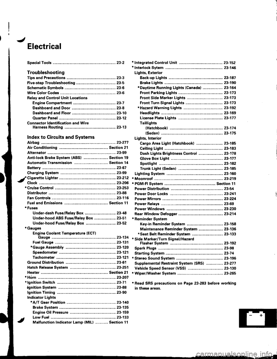
Spark Plugs ............................23-98
Starting System .....................23-74* Stereo Sound System ...,......,..........,...,......,.,.,.,..,., 23-196
Supplemental Restraint System (SRS) ................ 23-277
Vshicle Speed Sensor (VSS) ................................. 23.130r Wiper/Washer System .........................................., 23-265
*Read SRS precautions on Psge 23-283 before working
in those areas,
23-154
23.136
23"133
Page 1154 of 1680

lgnition System
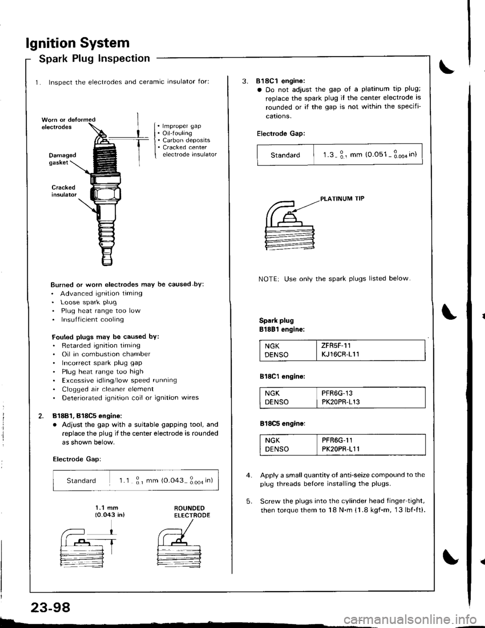
1. Inspect the electrodes and ceramic insulator for:
Spark Plug lnspection
. lmproper gap. Oil-fouling. Carbon deposits. Cracked centerelectrode insulatorDamagedgaskei
Burned or worn electrodes may be caused by:
. Advanced ignition timing. Loose spark plug
. Plug heat range too low. Insufficient cooling
Fouled plugs may be caused bY:. Retarded ignition liming. Oil in combustion chamber. Incorrect spark plug gap
. Plug heat range too high. Excessive rdling'low speed running
. Clogged air cleaner element. Deteriorated ignition coil or ignition wires
81881, 818C5 engine:
. Adjust the gap wjth a suitable gapping tool, and
replace the plug if the center electrode is rounded
as shown below.
Electrode Gap:
Standard 'l .1 ; r mm {0.043 ; ooa in)
E.
23-98
3.818C1 engine:
a Do not adjust the gap ol a platinum tip plug;
replace the spark plug it the center electrode is
rounded or if the gap is not within the specifi-
cattons.
Electrode Gap:
Standard I t.s-3., mm (0.051-3.oo4in)
5.
PLATINUM TIP
NOTE: Use onlv the spark plugs listed below
Spark plug
Bl88l engine:
NGK I ZFR5F-11
DENSO I KJ 16CR-111
818C1 engine:
NGK PFR6G-13
DENSO I PK2OPR-113
818C5 engine:
NGK PFR6G-I1
DENSO PK2OPR-111
Apply a small quantity ot anti-seize compound to the
plug threads belore installing the plugs.
Screw the plugs into the cylinder head tinger tight,
then torque them to 18 N.m (1 .8 kgf.m, 13lbf.ft).