Page 862 of 1680
Doors
Position Adjustment
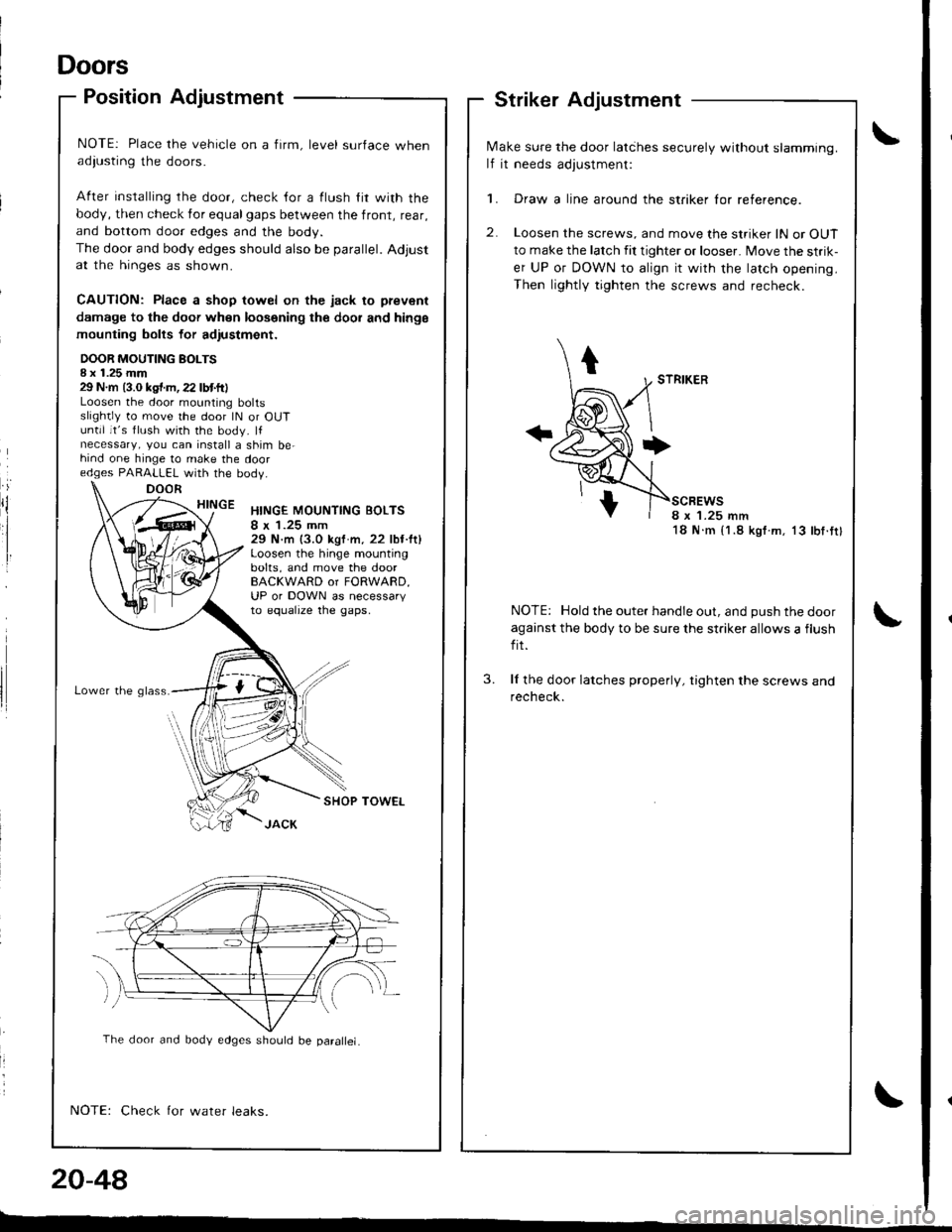
NOTE: Place the vehicle on a firm, level surface whenadiusting the doors.
After installing rhe door, check {or a flush lir with the
body, then check for equalgaps between the front, rear,
and bottom door edges and the body.
The door and body edges should also be parallel. Adjustat the hinges as shown.
CAUTION: Place a shop towel on the jack to prevenl
damage to the doof when loosening the dool and hinge
mounting bolts for adiustmont.
DOOR MOUTING BOLTSI x 1.25 mm29 N.m (3.0 kgt.m,22 lbtft)Loosen the door mounting boltsslightly to move the door lN or OUTuntil it's flush with the body. lfnecessary, you can install a shim be-hind one hinge to make the dooredges PARALLEL with the bodV.
HINGEHINGE MOUNTING BOLTS8 x 1.25 mm29 N.m (3.0 kgf m, 22 lbt.lt)Loosen the hinge mountingbolts, and move the doorBACKWARD or FORWARD,UP or DOWN as necessaryto equalrze tne gaps,
Lower the g lass.
SHOP TOWEL
Check for water leaks.
.iDOOR
N,4ake sure the door latihes securely without slamming.
lf it needs adjustment:
1. Draw a line around the striker lor reference.
2. Loosen the screws, and move the striker lN or OUT
to make the latch fit tighter or looser. Move the strik-
er UP or DOWN to align it with the latch opening.
Then lightly tighten the screws and recheck.
scBEws8 x '1.25 mm18 N.m {1.8 kgf.m. 13 lbf.tt}
NOTE: Hold the outer handle out, and push the door
against the body to be sure the striker allows a flush
fit.
ll the door latches properly, tighten the screws andrecheck.
3.
20-48
The door and body edges should be parallel.
-"
Page 866 of 1680
Replacement (cont'd)
4. Remove the actuator, then remove the screws.
<: Screw locations
A<: Screw, 3 B<: Screw, 2C { : Screw, 1
.aqm I- r'/
'.0=-l .g}_,,]
5.Turn the mirror base as shown, then remove Ine mtr
ror cover
MIRROR AASE
6. Installation is the reverse oI the removal procedure.
ACTUATOR
MIRROR COVEB
Mirrors
Mirror Visor and Mirror CoverRearview Mirror Replacement
:
rl
rl
I
20-52
L
1. Pry the cover off using the end of a flat tip screw-
drive r.
CAUTION: To prevent damage to the mirror and
cover, wrap the end ol the screwdriver with a shop
towel.
2. Remove the screws, then remove the rearview
mirror.
REARVIEWMIRROR
3. lnstallation is the reverse of the removal orocedure.
SHOP TOWEL
Page 867 of 1680
Windshield, Rear Window, Ouarter Glass
lndex
part names show the quantities of the parts Lrsed.
UPPER MOLDINGUPPER RUBBER DAM
CLIP E, 2 White
CLIP F, 2 Lett. WhiteBight. Blue
CLIP A, 8 Red
c
f(
RETAINER, 6 Orange
CLIP B, 2 Orange
CLIP C, 2 Black
LEFT SIDE MOLDING
CLIP D, 2 Green
AINER, 2 Yellow
WINOSHIELDRemoval, page 20,55Installation, page 20 56
REAR
GLASS BRACKET, 2
,^
,r"
A
RET
a
REAR WINDOW MOLDING
UPPER FASTENER, 2(Self-adhesive-type, glass side)
UPPER FASTENER,2(Self adhesive_type, hatch side)
SIDE RUBBERDAM, 2
OUARTER GLASSRemoval, Page 20-73
SPACER,2 Installation, Page 20-73
TAPE B, 2ADHESIVE
/
Ar-/
I
BUSHING SEAL.2
Removal, page 20-61Installation, page 20-62
NOTE: The numbers after the
Hatchback
RIGHT SIDE MOLDING
'l
@q
a
e,
Page 868 of 1680
Windshield, Rear Window
lndex
NOTE: The numbers alter the part names show the quantities of the parts used.
Sedan
UPPER MOLDING
RIGHT SIDE MOLDING
g
e
e
WINDSHIELDRemoval, page 20-55Installation, page 20-56
bq
BEAR WINDOWRemoval, page 20 68Installation,page 20-69
UPPER RUBBER DAM
CLIP E, 2 White
cLlP F, 2 Lefr. WhireRight. Elue
CLIP A, 8 Red
\
B)
fqLOWER RUBBERDAM
A
\
RET
g
REAR WINDOW MOLDING
GLASS BRACKET, 2AINER, 2 Yellow
UPPER FASTENER, 2(Self -adhesivo-type, glass side)
#,Krrr*
FA.TENER, 2(Clip-type, body side)
LOWER COVER
20-54
&....-r,o, sPAcER, 4
q*-------..- LowEB FA'TENER, 2
{Self-adhesive-typ€,slasssid€)
LOWER FASTENER, 2(Self-adhosive-type, body sidel
Page 875 of 1680
Rear Window
Removal
5.
6.
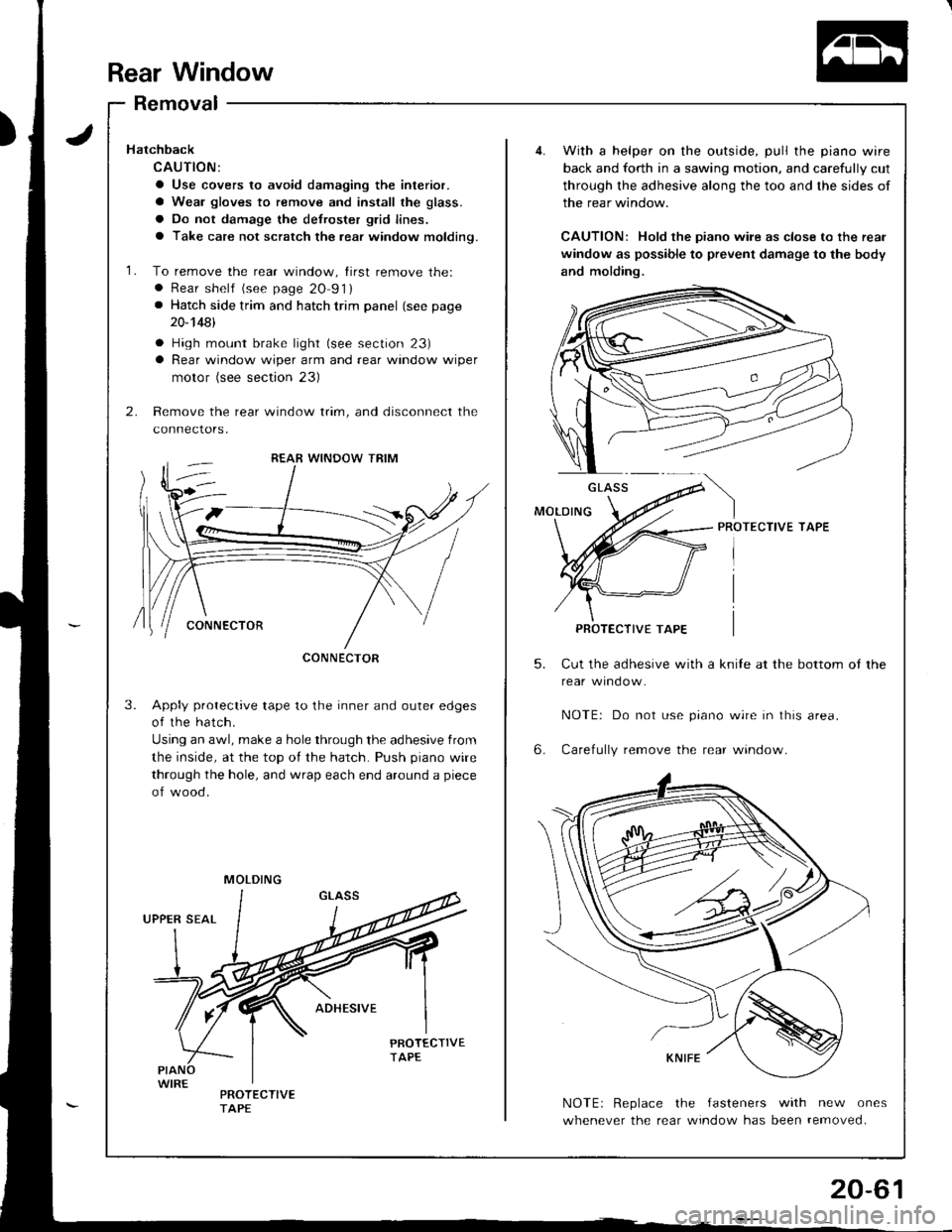
With a helper on the outside, pull the piano wire
back and forth in a sawing motion, and carefully cut
through the adhesive along the too and the sides of
the rear window.
CAUTION: Hold the piano wile as close to the rear
window as possible to prevent damage to the body
and molding.
PROTECTIVE TAPE
Cut the adhesive with a knile at the bottom ot the
NOTE| Do not use prano wrre In lhrs area.
Carefully remove the rear window.
NOTEr Replace the fasteners with new ones
whenever the rear window has been removed.
GLASS
PROTECTIVE TAPE
Hatchback
CAUTION:
a Use covers to avoid damaging the interior.
a Wear gloves to remove and install the glass.
a Do not damage the defroster glid lines.
a Take care not scratch the rear window moldino.
1. To remove the rear window, tirst remove the:. Rear shelf (see page 20 91). Hatch side trim and hatch trim panel (see page
20-14A1
a High mount brake light (see section 23)a Rear window wiper arm and rear window wiper
motor (see section 23)
2. Remove the rear window trim, and disconnect the
connectors,
Apply protective tape to the inner and outer edges
of the hatch.
Using an awl, make a hole through the adhesive from
the inside, at the top of the hatch. Push piano wire
through the hole, and wrap each end around a piece
of wood.
3.
CONNECTOR
MOLDING
Page 876 of 1680
Rear Window
{
lnstallation
2.
3.
Scrape the old adhesive smooth with a knife to a
thickness of about 2 mm {O.08 in) on the bonding
surface around the entire rear window opening
tlange.
NOTE:
a Do not scrape down to the painted surface of the
body; damaged paint will interlere with proper
bonding.
a Remove the upper and lower fasteners trom the
hatc n.
a Mask oft surrounding surfaces belore applying
primer.
Clean the hatch bonding surface with a sponge
dampened in alcohol.
NOTEr After cleaning, keep oil, grease or water from
getting on the surface.
lf the old rear window is to be reinstalled, use a put-
ty knite to scrape off alltraces of old adhesive, then
clean the rear window surlace with alcohol where
new adhesive is to be applied.
NOTE: Make sure the bonding surface is kept free
of water, oil and grease.
CAUTION: Avoid setling ths rear window on its
edges; the molding can be permanently detormed.
NOTE: Clean the shadowed area.
REAfi WINDOW
20-62
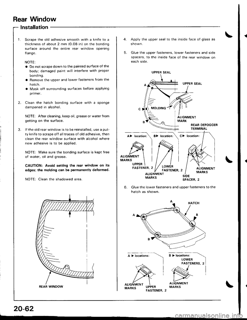
Apply the upper seal to the inside face of glass as
shown.
Glue the upper fasteners, lower lasteners and side
spacers, to the inside face of the rear window on
each side.
UPPER SEAL
MOLDING
5.
ALIGNMENTMARK
REAR DEFOGGERTEEMINAL
C> locaiion:
ALIGNMENTMARKSUPPER
ALIGNMENTMARKSALIGNMENTMARKS
;>t";",i".",
)
SIDESPACER,2
6.Glue the lower lasteners and uooer {asteners to the
hatch as shown.
a > i*"ri".* -\
LOWERFASTENERS, 2I
'N^ |
ALIGNMENTMARKSMARKS
UPPER SEAL
Page 877 of 1680
7.
9.
8.
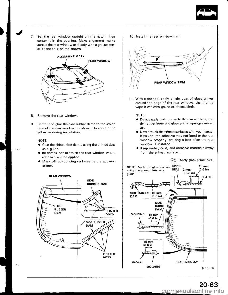
Set the rear window upright on the hatch, then
center it in the opening. Make alignment marks
across the rear window and body with a grease pen-
cil at the four points shown.
Remove the rear window.
Center and glue the side rubber dams to the inside
Iace of the rear window, as shown, to contain the
adhesive during installation.
NOTE:
a Glue the side rubber dams, using the printed dots
as a gurde.
a Be careful not to touch the rear window where
adhesive will be applied.
a Mask off surrounding surlaces betore applying
primer.
ALIGNMENT MARK
REAR WINDOW
1O. Install the rear window trim.
With a sponge, apply a light coat oI glass primer
around the edge of the rear window, then lightly
wipe it off with gauze or cheesecloth.
NOTEI
a Do not apply body primer to the rear window, and
do not get body and glass primer sponges mlxed
up.
a Never touch the primed surlaces with Your hands.
lf you do, the adhesive may not bond to the rear
window properly, causing a leak after the rear
window is installed.
a Keep water, dust, and abrasive materials away
lrom the primed surface.
't1.
NOTE: Apply the glass primer,
usjng the printed dots as agLrde,
7///r1 , eppY slass p mer here.
MOLDING 15 661{0.6 inl
(0.08 in)
UPPERSEAI 2 mm15 mm{O.6 in}
GLASS
lO.5 in)
MOLDING
REAR WINDOW
20-63
Page 878 of 1680
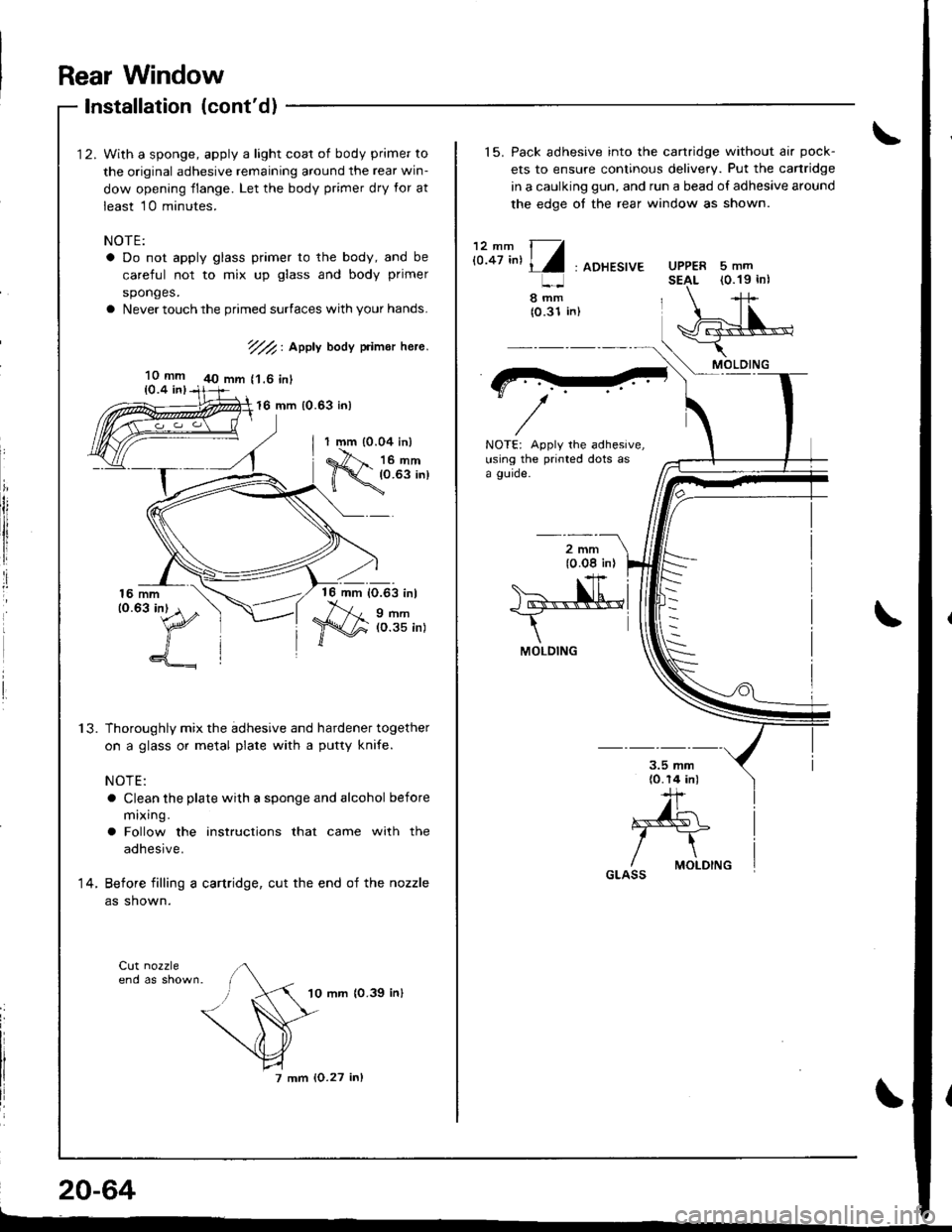
With a sponge, apply a light coat of body primer to
the original adhesive remaining around the rear win-
dow opening flange. Let the body primer dry for at
least 10 minutes.
NOTE:
a Do not apply glass primer to the body, and be
careful not to mix up glass and body primer
sponges.
a Never touch the primed surfaces with your hands.
7//2, Apply body primor here.
40 mm {'1.6 inl
16 mm (0.63 in)
ii
1 mm (0.04 inl
#;:;tT.,
1?
16 mm 10.63 inl
9 r'lm(O.35 in)
Thoroughly mix the adhesive and hardener together
on a glass or metal plate with a putty knife.
NOTE:
a Clean the plate with a sponge and alcohol before
mixing.
a Follow the instructions that came with the
adhesive.
Before filling a cartridge, cut the end of the nozzle
as shown.
10 mm 10.39 inl
7 mm {O.27 inl
14.
20-64
Rear Window
Installation (cont'd)
10 mm10.4 inl
L-
15. Pack adhesive into the cartridge without air pock-
ets to ensure continous delivery. Put the canridge
in a caulking gun, and run a bead of adhesive around
the edge of the rear window as shown.
i:.8r,^,4/: ADHE.,'E
NOTE: Apply the adhesive,using the printed dots asa gurde.
l0 Og in). +'F
>a--,N.h'*
IMOLDING
-r.]- |
^*{kL i
I "T^n i
5mm(0.19 inlUPPERSEAL
In,
!8(0
MOLDING
GLASS