Page 767 of 1680

Rear Brake Pads
Inspection and Replacement
Never use an air hose or dry b.ush to clean brake
assemblies.
Use an OSHA-approved vacuum cleaner to avoid
breathing brake dust.
Block the front wheels. loosen tha rear wheel nuts
slightly, support the rear of vehicle on sstety
stands, then remove the rear wheels.
Relaase the parking brake,
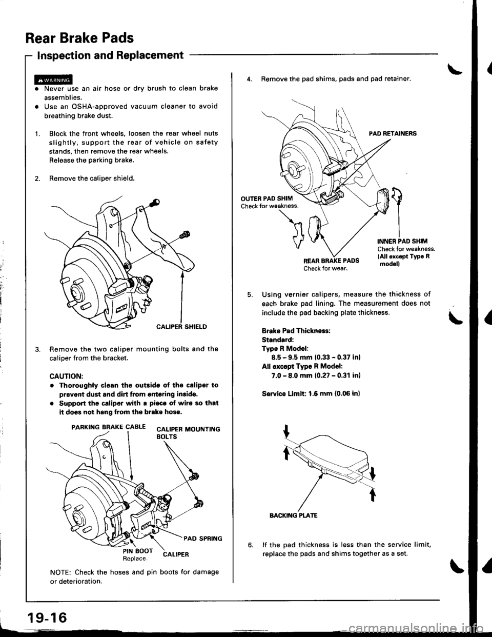
Remove the caliper shield.
Remove the two caliper mounting bolts and the
caliper trom the bracket.
CAUTION:
. Thoroughly clesn the out3ide ol tho csliper to
prsvent dust and dirt from entering in3ido,
. Support the caliper with a pi€c€ ot wire so that
it doss not hang lrom ths brako hose.
PARKING BRAKE CAALE cALtpEB MOUTTT|NGEOLTS
PAD SPRING
Replace.CALIPER
NOTE: Check the hoses and pin boots for damage
or deterioration.
\PIN EOOT
19-16
4. Remove the pad shims, pads and pad retainer.
PAD RETAINERS
'l
VINNER PAD SHIMCheck for weakness.(All exc.pt Type Rmod.ll
Using vernier calipers, measure the thickness of
each brake pad lining. The measurement does not
include the pad backing plate thickness.
Brake Pad Thickn..s:
Standard:
Typo R Model:
8.5 - 9.5 mm (0.33 - 0.37 in)
All except Type R Model:
7.0 - 8.0 mm {0.27 - 0.31 in)
Sorvie Limit: 1.6 mm {0.06 inl
BACKIiIG PLATE
lf the pad thickness is less than the service limit,
replace the pads and shims together as a set.
Page 769 of 1680

Inspection
rrii tlmm {0.4 inl10
l.
Rear Brake Disc
Disc Runout Inspection
Loosen the rear wheel nuts slightly, then raise the
vehicle and support it on safety stands. Remove the
rear wneers.
Remove the brake pads (see page 19-16).
Inspect the disc surface for damage or cracks. Clean
the disc thoroughly and remove all rust.
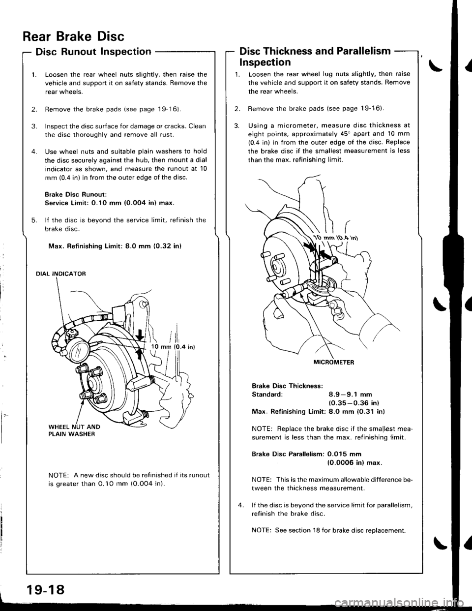
Use wheel nuts and suitable plain washers to hold
the disc securely against the hub, then mount a dial
indicator as shown, and measure the runout at 10
mm (0.4 in) in from the outer edge of the disc.
Brake Disc Runout:
Se.vice Limit: O.1O mm {0.0O4 in) max.
ll the disc is beyond the service limit, refinish the
brake disc.
Max. Refinishing Limit: 8.0 mm (0.32 in)
DIAL INDICATOR
NOTEi A new disc should be refinished if its runout
is greater than 0.'10 mm (O.O04 in).
Disc Thickness and Parallelism
Loosen the rear wheel lug nuts slightly, then raise
the vehicle and support it on safety stands. Remove
the rear wheels.
Remove the brake pads (see page 19-16).
Using a micrometer, measure disc thickness at
eight points, approximately 45" apart and 10 mm
(0.4 in) in from the outer edge of the disc. Replace
the brake disc if the smallest measurement is less
than the max. retinishing limit.
Bfake Disc Thickness:
Standard: 8.9 - 9.1 mm
(0.35-0.36 in)
Max. Refinishinq Limit:8.O mm (0.31 in)
NOTE: Replace the brake disc it the smaLlest mea-
surement is less than the max. retinishing limit.
Brake Disc Parallelism: O.O15 mm
(O.00O6 in) max.
NOTE: This is the maximum allowable difference be-
tween the thickness measurement.
lf the disc is bevond the service limit for parallelism,
refinish the brake disc.
NOTE: See section 18 for brake disc replacement.
\S rnrn .\'rn)
19-18
Page 770 of 1680

Rear Brake Caliper
Disassembly/Reassembly
o Never use an air hose or dry brush to clean brake assemblies.o Use an OSHA-approv€d vacuum cleaner to avoid breathing brake dust.. Conlaminated brake discs or pads reduce stopping ability.. When reusing the pads, always reinstall the brake pads in their original positions to prevent loss of braking efficiency,
CAUTION: Do not spill brake fluid on the vehicle; it may damags the paint; it brake fluid does contast the paint, wash itoff immediately with water,
NOTE:
. Coat the piston. piston seal, and caliper bore with clean brake fluid.. Beplace all rubber parts with new ones whenever disassembled.o Clean all parts in brake fluid and air dry; blow out all passages with compressed air.a Before reassembling, check that all parts are free of dust and other foreign particles.
. Replace parts with new ones whenever specified to do so.. Make sure no dirt or other foreign matter is allowed to contaminate the brake fluid.. Always use Genuine Honda DOT3 Brake Fluid. Using a non-Honda brake fluid can cause corrosion and decrease the lifeof the svstem.
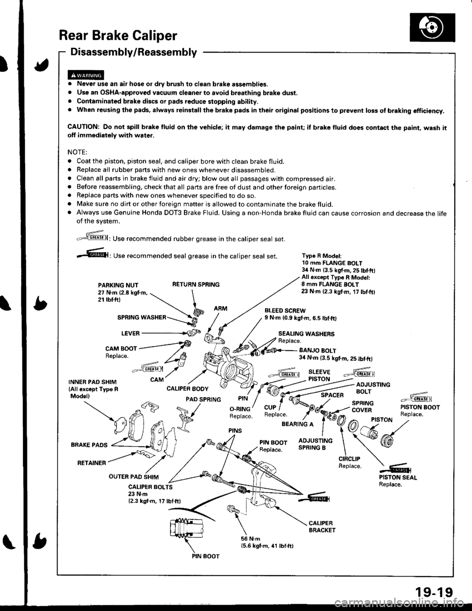
Type R Model:10 mm FLANGE BOLT34 N.m 13.5 kg{.m,25 tbtftlAll 6xc€pt Typ6 R Modet:8 mm FLANGE BOLT23 N.m {2.3 kgf.m, 17 tbf.ft)
BANJO BOLT3,0 N.m (3.5 kgt m, 2s tbtftl
Replace.
;,'"]@: Use recommended rubber grease in the caliper seal set.
.61, Use recommended seal grease in the catiper seal set.
PARKING NUTRETURN SPRING
27 N.m 12.8 kgt m, \2rtbt.frl \
ar"t"o *or"a"=-\9_r.r,e=
LEVER -------rCF
c^M Boor ---f
Re'lace
-==': /t8
"':sst /-
CALIPER BOLTS23 N.m12.3 kgf.m, 17 lbf.ft)
TNNERPADSHTM cAM
lAll except Typs R CALIPER EODYModel)
OUTER PAO SHIM
-db
PAD SPRTNG
a71 ^ V
BRAKEPA''
vUffifi*
,*,
^rrorr /Y'
,/ ^,
O.RINGBeplace.
PINS
BLEED SCREW9 N.m (0.9 kg{.m, 6.5 tbf.ft)
SEALING WASHERSReplace.
PIN BOOT
Page 776 of 1680
Gomponent Locations
,)
ABS CONTROL UNIT
UNDER.HOOD FUSE/RELAYRGHT-NEAR WHEELsEillioRaoxLEFT.REAR WHEEI-SENSOR
UNDER-H(X)D ABS
MODULATOR UNIT
FAIL-SAFE RELAY
RIGHT-FRONT WHEELSENSOR
LEFT-FROl{T WHEELSENSOR
UNDER.HOOD FUSE/RELAY BOX
ABS INDICATOR
UNDER.HOOD ABS FUSE/RELAY 8OX
ABS 81 {20 AI FUSEAAS MOTOR {40 Al FUS€
AAS PUMP MOTOR RELAY
GAUGE ASSEMBLY
!D
Dtrt]
HORN/STOP I2O A) FUSE
A8S UNIT {10 AI FUSERR DEF FI-Y I7.5 AI FUSE
19-25
Page 777 of 1680

.,i
,I
Anti-lock Brake SYstem (ABS)
when the brake pedal is depressed during driving, the wheels can lock before the vehicle comes to a stop. In such an event.
the maneuverability of the vehicle is reduced if the front wheels are locked, and the stability of the vehicle is reduced if the
rear wheels are locked, creating an extremely unstable condition. The ABS precisely controls the slip rate o{ the wheels to
ensUre maximum grip force from the tires, and it thereby ensures maneuverbiIity and stabiIity of the vehicIe.
The ABS calculates the slip rate of the wheels based on the vehicle speed and the wheel speed. then it controls the brake
fluid oressure to attain the target slip rate
Features/Gonstructio n
Grip Foact ot Ti.c tnd Rotd Surfuco
COEFFICIEUT OFFNIG"TPN
Slip Rrtr
BRAKINGSTART POINT
i'l
A: f'3t rp withoul .lip
B: SIDp.d dirt.nc.G Actu.ldtt nc.io.top
sr.n arrr = f =
STOP POINTTARGET SUP RATE
SUP FATEVEHICT.C S'EEO - wlCEL SPEED
NO: Notm.lly oP.n
l{C: Noirnrly qo..d
19-26
Page 782 of 1680
SEFVCECfiEC{CONMCIOF (2P)
Ecgq f to'o..,I dinFD OITA LrNiLTILU i -- CoNr€CToF Lr6P)8LU!L'sru-6J;:--l
8AN/OJ( ltx
44c'li1 c2o]_crol
IIHEEI SENSOf,-------61',^r
,--Ej.*
ABS CONTROL UNIT22P CONNECTOR{O numbedWHEEL SENSONCONNECTOR
FRONTJEIL.rGT;-r\
REAR
lr 2l
SERVICE CHECKCONNECTOR (2P)
1t 1l
ABS CONTROL UNIT 12P CONNECTOR(l number)n t=l
lr 2 3l4ls 6l
lrl Bl;iiltilld
618910tl
t2'14161llt9202122
DATA LINK CONN€CTOR{16P)
121315
19-31
Wire sids ot lemale tsrminals
Page 784 of 1680

Terminal
numbel
Wire
color
Terminalsign
lTerminal
name,
Description
Measurement
T€rminalConditions(lgnition switch ON {ll}}Vohage
BLKMHTGND4(Ground 4)
G round12-GNDBelow 0.3 V
14BRN(Service
check signal)
Detects service check con-
nector signal (DTC indica-
tion or DTC erasure)
I4-GNDSCS short
connector
ConnectedBelow 0.3 V
DisconnectedApprox. 5 V
16BRNfYELMCK(Motor check)
Detects pump motor drive
srg nal16-GNDPump motorONBattery voltage
OFFBelow 0.3 V
17LT BLU
RLW (+)
{Rear-left
wheel positive)
Detects left-rear wheel sen-
sor signal
17-18
q,
3
Turn wheel at
l turn/second
AC:
0.053 V or
above
oscilloscope:
0.15 Vp-p or
aoove
18GRY
RLW (_)
(Rear-left
wheel negative)
19GRNIVEL
RRW (+)
(Rearright
wheel positive)
Detects right-rear wheel
sensor srgnal
19-20
20BLU//EL
RRW (-)
(Rear-right
wheel negative)Stops0.25 - 1.15 V
21YEUGRNFSR
{Fail-safe relay)
Drives failsafe relay
(Fail-safe relay is turned
OFF to shut off the power
source to the solenoid and
pump motor relay when
problem occurs.)
21-GNDABS indicator
ONBelow 0.3 V
OFFApprox. 11V
LT BLU
DLC(Data link
connectorl
Communicates with Honda
PGM Tester22-GND
19-33
Page 785 of 1680

ABS Control Unit Terminal Arrangement
ABS CONTROL UNIT 12P CONNECTOR
Wire side of female terminals
Terminal
number
Wire
colot
Terminal sign
(Tsrminal
name,
Doscription
Measuromgnt
TerminalConditions
{lgnhion switch ON {ll)}Voltage
BLU/RED(Warning
ramp,
Drives ABS indicator
1.GNDABS indicatorON3-6V
OFFBelow 0.3 V
,BLKGNDl
{Ground 1)
Ground2-GNDBelow 0.3 V
BLI(ORN
RR-OUT(Rear-right
outlet)
Drives right-rear outlet
solenoid valve3-GND
a
OFFBattery voltage
YEUBLU
FL.OUT(Front-left
outlet)
Drives left-front outlet
solenoid valve4-GND
YEL/WHT
RL-OUT(Rearleft
outlet)
Drives left-rear outlet
solenoid valve5.GND
ONBelow 0.3 V
YEUBLK
FR-OUT
(Front-right
outlet)
Drives right-front outlet
solenoid valve6-GND
7BLKGND2
(Ground 2)
G rou nd7-GNDBelow 0.3 V
8YEL
RR-IN(Rear-right
inlet)
Drives right-rear inlet
solenoid valve8.GND
.9
-@
OFFBattery voltage
IRED/B LU
FL-IN(Front-left
inlet)
Drives left-front inlet
solenoid valve9-GND
l0RED/WHT
RL-IN
{Rearleft
inlet)
Drives left-rear inlet
solenoid valve1O-GND
ONBelow 0.3 V
11RED/BLK
FR] N(Front-right
inlet)
Drives right-front inlet
solenoid valve11-GND
't2YEURED
PMR
{Pump motor
retay)
Drives pump motor relay
12-GND.9
.EU'@
OFFdE
ONBelow 1.0 V
OFFBattery voltage
ONBelow 0.3 V
19-34