Page 745 of 1680
L
I
Rear Damper
Removal
Remove the rear wheels (see page 18-30).
Remove the damper access panel.
- Sedan only: Remove the trunk side panel (see
section 20).
Remove the two flange nuts.
Hatchback:
DAMPER ACCESS PANEL
10 x'1.25 mm
Remove the wheel sensor wire brackets (for vehicles
with ABS).
NOTE: Do not disconnect the wheel sensor connec-
tor.
18-36
5.Remove the flange bolt on the damper.
Remove the flange bolt that connects the lower arm
to the trailing arm.
7. Lower the rear suspension and remove the damper.
DAMPER
\
Page 747 of 1680

Rear Damper
Disassembly/lnspection {cont'd}
Inspestion
All oxcspt Typo R Models:
DAMPERMOUNTING
Check for
Check Ior weaknessand damag6.
DAMPERRUEBERCheck ford€t6riorationano damage.
DAMPER MOUNTINGCOLLAR
DAMPER
SELF.LOCKING NUT10 x 1.25 mm29 N.m 13.0 kgf.m, 22 lbt'ft)R6place.
Type R Model:
BUMP STOP PLATE
SELF-LOCKING NUTt0 r 1.25 mm29 N.m (3.o kgt m, 22 lbf'ft)Rep|aco. -.\-.--...\
_____6
DAMPTRMoUNnNG -.-__re
Check fordeterioration DAMPERMOUNnNG -----+,and damag6. @L!AR Ag-
liillffi*"*,--@
DAMPTR MoU.{nNG __-_____*e
DUST COVEBCh6ck for b€ndingand oamage.
DUST OOVER BOOTCh€ck for deterioralionand damage.
MOUNNNG BASE
DAMPEB MOUNTINGRUBBERCheck lordeteriorationano oamage.
SPRING MOUNTINGRUBBERCheck for deteriorationano oamage.
Check for weakness,compression and damage.
DUST COVER PLAT€
DUST COVERCheck for bendingano oamage.
DUST COVER BOOTChock for deteriorationano oamage,
AUMP STOP PLAYE
1€')
I t_--tlg:z
q._
Y
Check for weaknessand damage.
BUMP STOP
18-38
DAMPER UNTTDAMPER UN]T
Page 749 of 1680

Rear Damper
Lower the rear suspension and position the damper
with the welded nut pointed toward the front of the
vehicle.
DAMPER
2. Loosely install the two flange nuts.
Hatchback:Sedan:
lnstallation
. ',.?7,:..r9\,ir '..
EY
FLANGE NUTS10 x 1.25 mmTighten these nuts in step 7 on the next page.
18-40
3. Install the wheel sensor wire bracket.
NOTE: Be careful when installing the sensors to
avoid twisting wires.
Raise the rear suspension with a floor iack until the
vehicle just lifts off the safety stand.
@ The floor jack must be securely posi-
tionod or personal iniury may result.
5. Install the damper mounting bolt and the flange
bolt, then tighten the bolts.
NOTE: The damper mounting bolt and the flange
bolt should be tightened with the damper under
vehicle load.
FLANGE EOLT10 x 1.25 m.n54 N.m (5.5 kgf m, 40 lbt.ftl
FLANGE BOLT10 x 1-25 mm54 N.m ls.s kgf m, 40 lbtft)
6. Tighten the three wheel sensor wire bracket bolts
{for vehicles with ABS).
9.8 N.m {1.0 kg{.m, 7.2 lbtftlBOLTS
Page 750 of 1680
1.Tighten the two flange nuts on top of the damper to
the specified to.que.
Install the damper access panel by aligning the tabs
on the panel.
Sedan only: Install the trunk side panel (see section
FLANGE NUTS10 x 1.25 mm49 N.m {5.0 kgt.m, 36lbl.ft)
10. Install the rear wheels {see page l8-32).
18-41
Page 752 of 1680

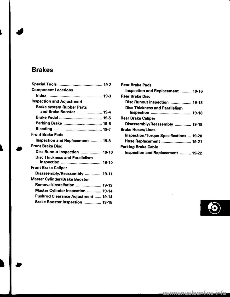
Brakes
Special Tools ............. 19-2
Component Locations
Index ................ ...... 19-3
Inspection and Adiustment
Brake system Rubber Parts
and Brake Booster ....................... 19-4
Brake Pedal ............ 19-5
Parking Brake ........ 19-6
Bleeding ................. t9-7
Front Brake Pads
Inspection and Replacement .......... l9-B
Front Brake Disc
Disc Runout Inspection ................... 19-10
Disc Thickness and Parallelism
Inspection .......... 19-10
Front Brake Caliper
Disassembly/Reassembly ............... l9-1 l
Master Cylinder/Brake Booster
Removal/1nsta|lation ....................... 19-13
Master Cylinder Inspection ............. 19-14
Pushrod Clearance Adjustment ...... 19-14
Brake Booster Inspection,.............,, lg-15
Rear Brake Pads
Inspeetion and Replacement .......... l9-16
Rear Brake Disc
Disc Runout Inspection ................... 1 g-18
Disc Thickness and Parallelism
Inspection .......... t9-18
Rear Brake Caliper
Disassembly/Reassembly ............... l9-19
Brake Hoses/Lines
Inspection/Torque Specifications ... l9-20
Hose Replacement ...................... ..... 19-21
Parking Brake Gable
f nspection and Replacement ,......,.,19-22
Page 754 of 1680
Component Locations
Index
FRONT BRAKESFront Brake Pads, page 19-8Front Brake Disc, page 19-10Front Brake Caliper, page 19-11
BLAKE HOSES/LINESInspection/Torque Specitications. page 19,20Hose Replacement, page 19-21
MASTER CYLINDEBR€moval/lnstallation, pag€ 19-'t3Mast€r Cylinder Inspection, page 19-14Pushrod Cl6aranc6 Adjustment, page 19-14BRAKE BOOSTERBrake Eoostor Inspoction, page 19-15Removal/lnstallation, pags'19-'13
BMKE PEDALlnspection andAdjustment, page 19-5
PARKING ERAKEAdjustment, page'19-6PARKING BRAKE CABLElnspoction and Roplacement, page 19-22
REAR DISC BRAKESRear Brake Pads, page 19-16Rear Brake Disc, page 19-18Rear Brake Caliper, page 19-19
19-3
Page 757 of 1680

Inspection and Adiustment
Parking Brake
Inspection
1. Pull the parking btake lever with 196 N
lbf) of force to Jully apply the parking
parking brake lever should be locked
soecified notches.
Lever Locked Notches: 6- l0
{20 kgf, 44
brake. The
within the
Pulled up with 196 N {2O kgf, 44 lbf)
LEVER LOCKED NOTCHES
2, Adjust the parking brake if the lever notches are out
of specification.
Adjustment
NOTE: After rear brake caliper servicing.loosen the park-
ing brake adjusting nut, start the engine, and depress the
brake pedal several times to set the self-adjusting brake
before adiusting the parking brake
1. Raise the rear wheels oIt the ground. and suppon
the car on safety stands.
!!@ ato"t the trort whoels bsfore jacking
up the roal ot tha car'
2. Make sure the parking brake arm on the rear brake
caliDer contacts the brake caliper pin.
19-6
8.
3. Pullthe parking brake lever up one notch'
Remove the rear console {see section 20)'
Tighten the adjusting nut until the rear wheels drag
slightly when turned.
7.
Release the parking brake lever fully, and check that
the rear wheels do not drag when turned. Readjust
if necessary.
Make sure the parking brakes are fully spplied when
the parking brake lever is pulled up fully.
Install the cap onto the parking brake cable end, and
reinstall the rear console.
Page 758 of 1680

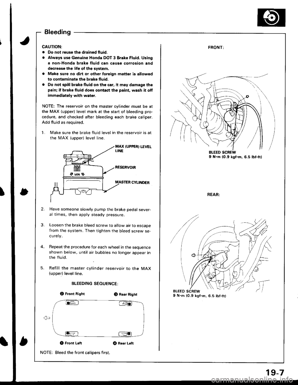
Bleeding
CAUTION:
. Oo not reuse the drsined fluid,
. Always use Genuine Honda DOT 3 Brake Fluid. Using
a non-Honda brake fluid can cause corrosion and
decrease the lile of the system,
a Make sure no dirt or other foreign matt€t is allowed
to contaminate the brske fluid.
. Do not spill brake fluid on tho car, it may damage the
pain; if brake fluid does contact the paint, wash it off
immediately with water.
NOTE: The reservoir on the master cylinder must be at
the MAX (upper) level mark at the start of bleeding pro-
cedure, and checked after bleeding each brake caliper.
Add fluid as required.
1. Make sure the brake fluid level in the reservoir is at
the MAX (upper) level line.
MAX (UPPER) I.IVELLINE
CYIINDER
Have someone slowly pump the brake pedal sever-al times, then apply steady pressure.
Loosen the brake bleed screw to allow air to escapefrom the system. Then tighten the bleed screw se-curely.
Repeat the procedure for each wheel in the sequenceshown below, until atr bubbles no longer appear inthe fluid.
Refill the master cylinder reservoir to the MAX(upperl level line,
BLEEDING SEOUENCE:
e, Front RightO Roa. Right
O Front Left Gt Raar L€ft
Bleed the front calipers first.NOTE:
19-7
FRONT:
REAR:
9 N.m {0.9 kgI'm,6.5 lbt.fr)
/
lc
,,
l,