Page 706 of 1680
Power Steering Gearbox
Reassembly (cont'dl
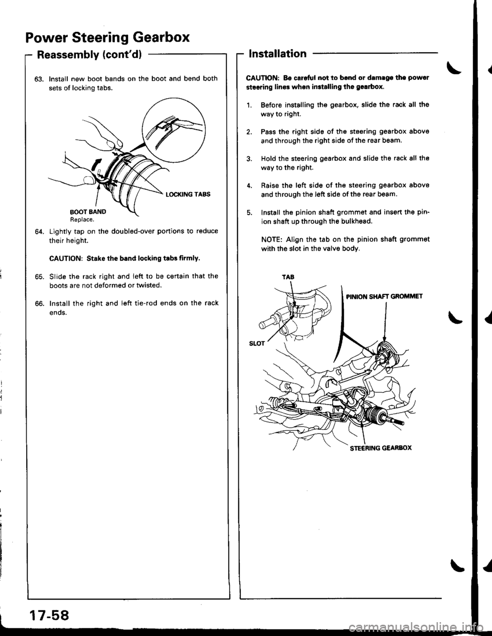
63. Install new boot bands on the boot and bend both
sets of locking tabs.
Lightly tap on the doubled-over portions to reduce
their height.
CAUTION: Stake ihe bsnd locking tabs tirmly.
Slide the rack right and ieft to be certain that the
boots are not deformed or twisted.
Install the right and left tie-rod ends on the rack
enos.
64.
lnstallation
CAUTION: Bo caretul not to bond or damrge the powcr
steering lines when in3t8lling the grlrbox.
1. Before installing the gearbox, slide the rack all the
way to right.
2, Pass the right side of the stsering gearbox above
and through the right side of the rear beam.
3. Hold the steering gearbox and slide the rack 8ll the
way to the right.
4. Rsise the left side of the steering gearbox above
and through the left side of the rear beam.
5. Install the pinion shaft grommet and insert the pin-
ion shaft up through the bulkhesd.
NOTE: Align the tab on the pinion shaft grommet
with the slot in the valve bodY.
oo.
tAa
17-58
Page 708 of 1680
Power Steering Gearbox
Installation (cont'dl
11. Install the steering joint cover with the clamps and
clips.
lnstall the rear beam brace rod and return line
clamp on the rear beam.
NOTE: lnstall the rear beam brace toward the
return line clamp.
12.
CLIP
38 N.m 13.9 kgl'm,28 lbf tl)
17-60
13. Install the three way catalytic converter with the
new gaskets and new self-locking nuts, and connect
the secondary heated oxygen sensor (HO2S) con-
nector.
SECONOARYHEATED OXYGEN SENSOR CONNECTOR
22 N.m {2.2 kgf.m, 16lbIft)
Connect the shift linkage (M/T model: see section
13, A,,/T model; see section 14).
Thread the right and left tie-rod ends onto the rack
an equal number of turns.
14.
Page 710 of 1680
Suspension
Special Tools ............. 18-2
Component Location
lndex ................ ...... 18-3
Wheel Alignment
Caster ............... ...... 18-4
Camber .................. 18-4
Front Toe Inspection/
Adjustment ........ 18-5
Rear Toe Inspection/
Adiustment ........ 18-5
Turning Angle Inspection ................ 18-6
^'heel/Hub Inspection
tBearing End Play .............................. 18-7
Wheel Runout ....... 18-7
Front Suspension
Torque Specifications ...................... 18-8
Knuckle/Hub
lllustrated lndex .........,................. 18-9
Knuckle Removal ......................... 18-11
Wheel Bearing Replacement ...... 18-14
Knuckle 1nsta11ation ..................... 18-16
Lower Ball Joint Replacement ....... 18-17
Ball Joint Boot Replacement .......... 18-19
Suspension Arms
Removal/lnspection .................... 18-20
lnstallation ......... 18-21
Front Dampel
Removal ................. 18-22
Disassembly/lnspection ............. ..... 18-22
Reassembly ........... 18-24
fnstaffation ............. 1A-25
Rear Suspension
Torque Specifications ...................... 18-26
Hub Bearing Unit
f f f ustrated lndex ................ ........... 18-27
Removal ............. 18-29
lnstallation ......... 18-30
Suspension Arms
Removal/lnspection .................... 18-32
lnstallation ......... 18-34
Rear Damper
Removal ................. 18-36
Disassembly/lnspection .................. 18-37
Reassembly ........... 18-39
Installation ............. 18-40
Page 712 of 1680
Component Location
lndex
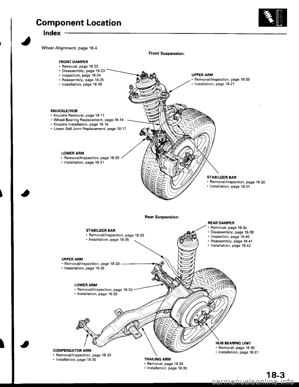
Wheel Alignment, page 18-4
FRONT DAMPER. Removal, page 18 23' Disassembly, page 18-23. Inspection, page 18-24. Reassembly, page 18-25. lnstallation. page 18 26
KNUCKLE/HUB. Knuckle Removal, page 18-11'Wheel Bearing Replacement, page 18-14' Knuckle lnst6llation, page 18-16. Lower BallJoint Replacement, page 18-17
LOWER ARM. Removal/lnspection, page 18-20. lnstallation, page l8 21
Front SusDonsion:
Rear Susoension:
UPPER ARMRemoval/lnspection, page 18-20Installation, page 18-21
STABILIZER BARRemoval/lnspectaon, page 18-33Installation, page 18-35
STABILIZER BARRemoval/lnspection, page 18-20Installation, page 18,21
REAR DAMPER. Removal, page 18-3o. Disassembly, page 18-39' Inspection, page 18-40. Reassembly, page l8-41. Installation, page 18,42
UPPER ARM. Removal/lnspection, page l8 33. Installation, page 18-35
LOWER ARM. Removal/lnspection, page 18,33. lnstallation, page 18-35
ICOMPENSATOR ARM. Removal/lnspection, page 18 33. Installation, page 18-35
HUB BEARING UNIT. Bemoval, page 18'30. Installation, page 18,31
TRAILING ARM. Removal, page 18-33. lnstallation, page 18-35
18-3
Page 713 of 1680
Wheel Alignment
Caster
NOTE: For proper inspection/adjustment of the wheel
alignment check and adjust the following before check-
ing the alignment.
. Check that the susoension is not modified.
. Check the tire size and tire pressure.
. Check the runout of the wheels and tires.
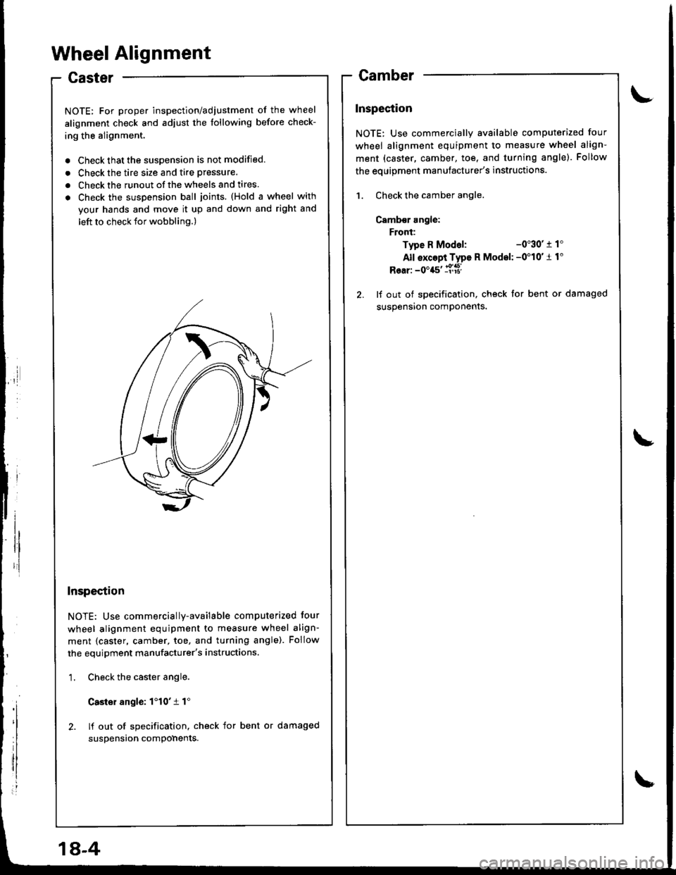
. Check the suspension ball joints. (Hold a wheel with
your hands and move it up and down and right and
left to check tor wobbling.)
Inspection
NOTE: Use commercially-available computerized four
wheel alignment equipment to measure wheel align-
ment {caster, camber, toe, and turning angle). Follow
the equipment manufacturer's instructions.
1. Check the caster angle.
Casler angle: 1'10't 1"
2. lf out of specification. check for bent or damaged
suspension compohents.
Camber
Inspection
NOTE: Use commercially available computerized four
wheel alignment equipment to measure wheel align-
ment (caster, camber, toe, and turning angle). Follow
the eouioment manufacturer's instructions.
1. Check the camber angle.
Camb€r angle:
Front:
Type R Modal:-0"30' r 1'
All exc6pi Type R Model: -0'10'1 1"
Rear: -0'45' ll['a8l
2. lf out of specification, check for bent or damaged
susoension comDonents.
1A-4
Page 714 of 1680
\
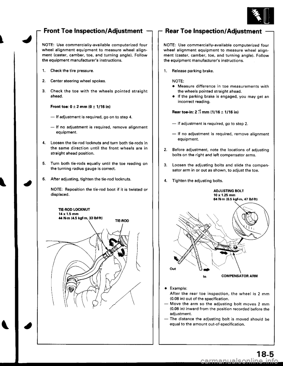
Front Toe Inspection/AdjustmentRear Toe Inspection/Adjustment
NOTE: Use commercially-available computerized four
whesl alignment equipment to measure wheel align-
ment (caster, camber, toe. and turning angle). Follow
the equipment manufacturer's instructions.
1.
2.
Check the tire pressure.
C€nter steering wheel spokes.
Check the toe with the wh€els pointed straight
ahead.
Front to6: 0 i 2 mm (0 t 1/16 in)
- lf adjustment is required. go on to step 4.
- lf no adjustment is required, remove alignment
equrpm€nr,
Loosen the ti€-rod locknuts and turn both tie-rods in
the same direction until the front wheels are in
straight ahead position.
Turn both tie-rods equally until the toe reading on
the turning radius gauge is correct.
After sdjusting, tighten the tie-rod locknuts.
NOT€: Reposition the tie-rod boot if it is twisted or
displaced.
TIE-ROD LOCKNUT14 x 1.5 mm
6.
a
NOTE: Use commercially-available computerized four
wheel alignment equipment to measure wheel align-
ment (caster, camber, toe, and turning angle), Follow
the equiDment manufacturer's instructions.
1. Release parking brake.
NOTE:
. Measure difference in toe measurements with
the wheels pointed straight ahead.
. lf the parking brake is engaged. you may get an
incorrect reading.
Rear toe-in: 2 11 mm l1l16 i 1/15 in)
- lf adjustment is required, go to step 2.
- lf no adjustment is required, remove alignment
equipment.
Before adjustment, note the locations of adjusting
bolts on the right and left compensator arms.
Loosen the adjusting bolts and slide the compen-
sator arm in or out as shown, to adjust the toe.
Tighten the adjusting bolts.
ADJUSTING BOLT10 x 1.25 mm
COMPENSATOR ARM
. Example;
A{ter the rear toe inspection, the wheel is 2 mm(0.08 inl out of the soecification.- Move the arm so the adjusting bolt moves 2 mm(0.08 inl inward from the position recorded betore theadjustment.- The distance the adjusting bolt is moved should be
equal to the amount out-of-specification.
6a N.m 16.5 kgt m, 47 lbt.ft)
a4 N.m la.s kgI.m, 33 lbf.ft)
18-5
Page 716 of 1680
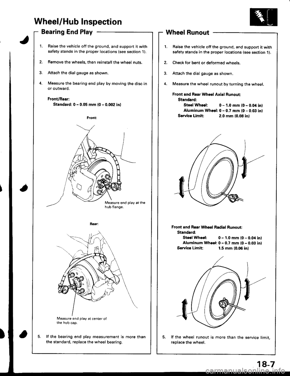
Wheel/Hub Inspection
Bearing End Play
Raise the vehicle off the ground, and support it with
safety stands in the proper locations (see saction 1).
Remove the wheels, then reinstallthe whe6l nuts.
Attach the dial gauge as shown.
Measure the bearing end play by moving the disc in
or outward.
Front/Rear:
Standa.d: 0 - 0.05 mm (0 - 0.qr2 in)
a
Measure end play at center ofthe hub cap.
lf the bearing end play measurement is
the standard, replace the wheel bearing.
Wheel Runout
Raise the vehicle off the ground, and support it withsatety stands in the proper locations (see section 1).
Check for bent or deformed wheels.
Attach the dial gauge as shown.
Measure the wheel runout by turning the wheel.
Front and Roar Whool Axial Runout:
Standard:
Stcsl Whoel: 0 - 1.0 mm (0 - 0.04 inl
Aluminum Whcel: 0 - 0.7 mm (0 - 0.03 inl
Sorvlc. Limit:2.0 mm (0.08 inl
Front End Roar Whod Rldisl Runouti
Standard:
Ste.l Whool: 0 - 1.0 mm (0 - 0.04 inlAluminum Wh.el: 0 - 0.7 mm (0 - 0.03 inl
Sorvico Limit:1.5 mm (0.06 inl
lf the wh€el runout is more than the service limit,
reDlace the wheel.
more than
18-7
Page 735 of 1680
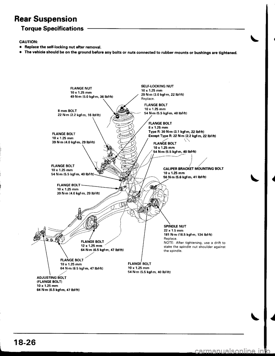
Rear Suspension
Torque Specifications
CAUTION:
. Replace the solt.locking nut after removal.
. The vohicle should be on th€ ground beto.6 any bolts or nu$ connected to lubber mounts or bushings are tight€ned.
FLANGE BOLT10 x 1.25 mm39 N.m {4.0 kgl.m,29lbtft}
FLANGE BOLT10 x 1.25 mm54 N.m (5.5 kg,f.m, 40
FLANGE BOLT10 x 1.25 mm
I mm BOLT22 N.m (2.2 kgf m, 16 lbf.ft)
FLANGE NUT10 x 1.25 mm49 N.m 15.0 kgf.m,35lbtft)
FLANGE SOLT12 x 1.25 mm
SELF.LOCKING NUTl0 x 1.25 mm29 N.m 13.0 kgt.m,22 lbf.ft)Beplace.
FLANGE BOLT'10 x 'l.25 mm54 N.m {5.5 kgl.m.40 lbtft}
FLANGE BOLTI x 1.25 mmTyp6 R: 30 N.m (3.1 kgf.m,22 lbtft)Except Typ6 R: 22 N.m 12.2l'gl'rn,2.lbiftl
FLANGE SOLT10 r L25 mm5,1N.m (5.5 kg{.m, .0 lbf.ftl
CALIPER BRACKET10 x 1,25 mm56 N.m (5.6 kgf.m. 41 lbl.ftl
NUT
MOUNTING
39 N.m 14.0 kgl m,29 lbtftl
BOLT
22 x 1.5 mm181 N.m {18.5 kgf.m, 134lbf.ft}Replace,NOTE: After tightening, use a drift rostake the spandle nut shoulder againstthe spjndle.64 N.m (6.5 kgl.m, 47 lbtftl
EOLT10 x 1.25 mm64 N.m (6.5 kgl.m, 47 lbtftl
FLANGE BOLTl0 x 1.25 mm54 N m 15.5 kgt m, 40 lbf.ft)
ADJUSTING BOLTIFLANGE BOLTI10 x 1.25 mm64 N.m (6.5 kg{.m, 47 lbf.ft,
18-26