1998 ACURA INTEGRA battery replacement
[x] Cancel search: battery replacementPage 35 of 1680

Lubrication Points
No. LUBRICAnON POINTSLUBRICANT
1 E^g,neAPI Service Grade: Use SJ "Energy Conserving" orSH "Energy Conserving ll" grade oil,The oil container may also display the API Certificationmark shown below. Make sure it savs "For GasolineEngines. "
SAE Viscositv: See chart below.
2TransmissionManualHonda Genuine MTF*1
AutomaticGenuine Honda Premium Formula AutomaticTransmission Fluid (ATF)*,
Brake line (lncludes Anti-lock brake line)Genuine Honda DOT3 Brake Fluid13
Clutch lineGenuine Honda DOT3 Brake Fluid*3
Power steering gearboxSteering grease P/N 08733 - 8070E
Release fork lManual transmission)Sup€r High Temp Urea Grease (P/N 08798 - 9002)
1
8
Throttle wire end (Dashboard lower oanel hole)Cruise control actuator wire end(Dashboard lower Danel hole)Silicone grease
o
10
11
14
Throttle cable end (Throttle link)Cruise control actuator cable end (Actuator link)Brake master cvlinder oushrodClutch master cylinder pushrod
Battery terminals
Fuel fill lid
Multi-purpose grease
to
17
18
Engin6 hood hinges and engine hood latchHatch hinges 8od latch or trunk hinges and latchDoor hjnges, upper and lowerDoor ooen detent
Honda White Lithium Grease
19Rear b.ake calipersSilicone grease
20Power steering systemGenuine Honda Power Steering Fluid-V or S*.
21Ai|' conditioning compressorRefrigerant oii ND-O|L8 {P/N38897 - PR7 - A01AH or38899-PR7-A01)(For Refrigerant: HFC-134a (R- 134a))
API SERVICE LABELAPI CERTIFICATION SEAL
Recommended engine oilEngin€ oil viscosity lorambrent lemperature ranges
r(For the details of lubrication points and type of lubricants to be applied, refer to the illustrated index and various work Dro-cedure (such as Assembly/Reassembly, Replacement, Overhaul, Installation. etc.) contained in each section,
*1: Always use Genuine Honda Manual Transmission Fluid (MTF). Using motor oil can cause stiffer shifting because itdoes not contain the proper addtuves.*2: Always use Genuine Honda Premium Formula Automatic Transmission Fluid (ATF). Using a non-Honda ATF can affectshift quality.*3: Always use Genuine Honda DOT 3 B.ake Fluid, Using a non-Honda brake fluid can cause corrosion and decrease thelife of the system.'4: Always use Genuine Honda Power Steering Fluid-V or S. Using any other type of power steering fluid or automatictransmission fluid can cause increase v,/ear and poor steering in cold weather.
L(
{
4-2
Page 326 of 1680

rr*
Fuel Supply System
Fuel Filter
Replacement
Do not smoke while working on fuel system. Koop
open flame away from your work atea.
While replacing the fuel filter, be qaretul to keep a
sate distanco between battery terminals and any
tools.
The fuel filter should be replaced whenever the fuel
pressure drops below the specified value I27o - 32O kPa,
2.8 - 3.3 kgf/cm', 40 - 47 psi (B18C'1, B l8C5 enginesi 320- 370 kPa (3.3 - 3.8 kgtcm'�,47 - 54 psi) with the fuel
pressure regulator vacuum hose disconnected and
pinchedl aiter making sure that the tuel pump and the
fuel pressure regulator are OK.
Place a shop towel under and around the fuelfilter.
Relieve fuel pressure {see page 11-1'18}.
Support the fuel filter with a wrench, as shown,
then remove the 12 mm banjo bolt and the tuel feed
pipe lrom the fuelfilter.
Remove the fuel filter clamp and fuel filter.
lnstall the new fuel filter in the reverse order of
removal, and note these items:
. When assembling, use new washers as shown.
. Clean the tlared joint of high pressure hoses
thoroughly before reconnecting them.
\,,
9.8 N.m {1.0 kgf.m,7.2 tbf.frl
WRENCH
12 mm BANJO BOLT33 N.m 13.4 kgf.m. 25 lbl.ftl
37 N.m (3.8 kgf.m,27 lbf.ft)
Page 503 of 1680
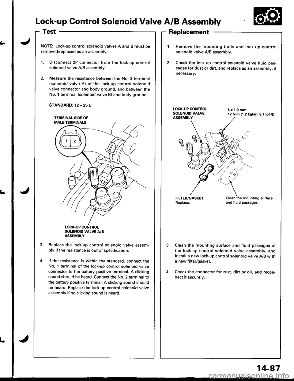
Replacement
(.
L
Lock-up Control Solenoid Valve A/B Assembly
NOTE: Lock-up control solenoid valves A and B must be
removed/replaced as an assembly.
L Disconnect 2P connector from the lock-up control
solenoid valve Ay'B assembly.
2. Measure the resistance between the No. 2 terminal
{solenoid valve A) of the lock-up control solenoid
valve connector and body ground, and between the
No. 1 terminal {solenoid valve B) and body ground.
STANDARD: 12 - 25 O
LOCK.UP CONTROLSOLENOID VALVE A/BASSEMBLY
Replace the lock-uo control solenoid valve assem-
bly if the resistance is out of specification.
lf the resistance is within the standard, connect the
No. 1 terminal of the lock-uD control solenoid valve
connector to the battery positive terminal. A clicking
sound should be hea.d. Connect the No. 2 terminal to
the battery positive terminal. A clicking sound should
be heard. Replace the lock-up control solenoid valve
assembly if no clicking sound is heard.
1.Remove the mounting bolts and lock-up control
solenoid valve A/B assemblv.
Check the lock-up control solenoid valve fluid pas-
sages for dust or dirt. and replace as an assembly, if
necessary.
6x1.0mm12 N.m (1.2 kgtm,8.7 lbf.ftl
Clean the mounting surfaceand tluid passages.
Clean the mounting surface and fluid passages of
the lock-up control solenoid valve assembly, and
install a new lock-up control solenoid valve Ay'B with
a new filter/gasket.
Check the connector for rust, din or oil, and recon-
nect it securelv.
l-
14-87
Page 504 of 1680
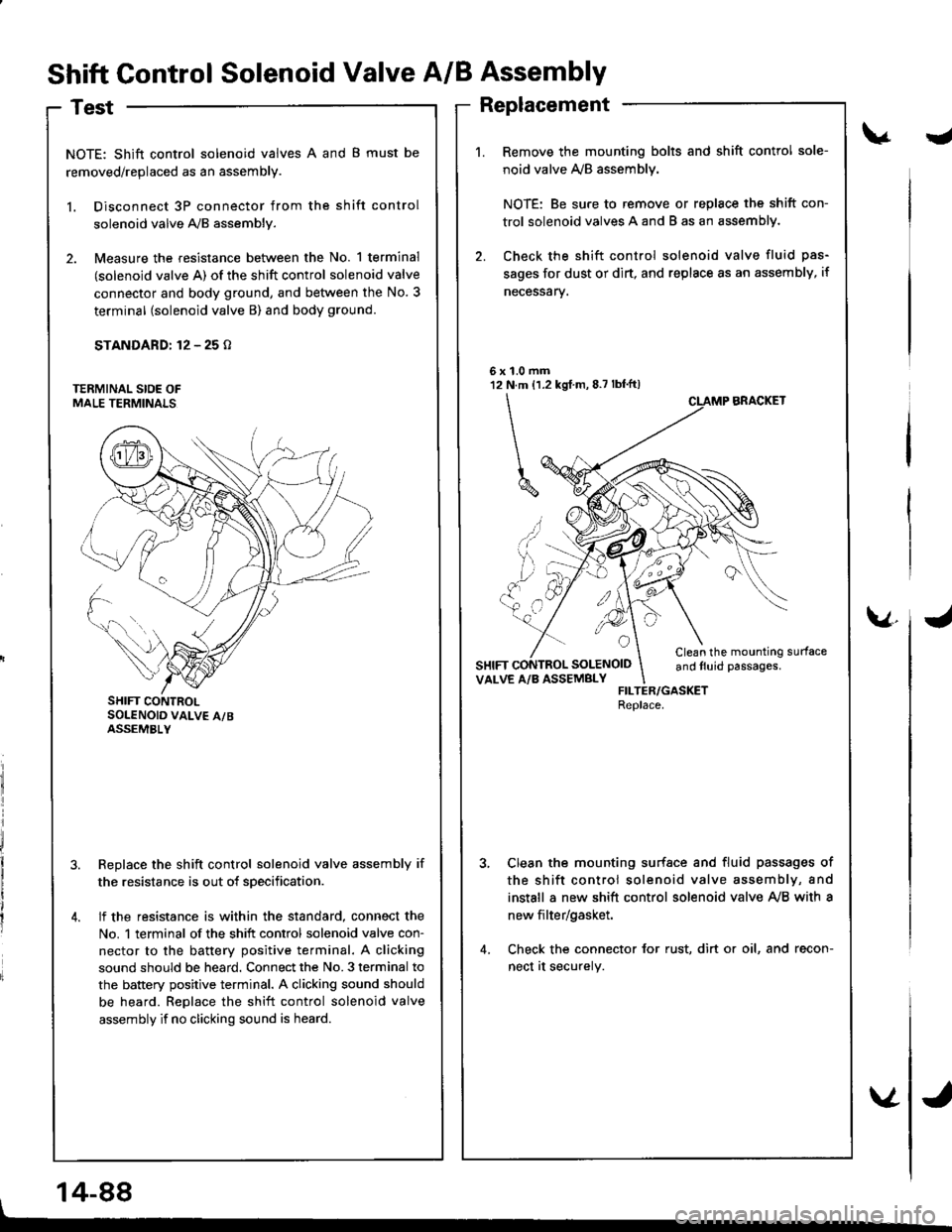
Shift Control Solenoid Valve A/B Assembly
Test
NOTE: Shift control solenoid valves A and B must be
removed/replaced as an assembly.
l. Disconnect 3P connector from the shift control
solenoid valve A,/B assembly.
2. Measure the resistance between the No. 1 terminal
(solenoid valve A) of the shift control solenoid valve
connector and body ground, and between the No. 3
terminal (solenoid valve B) and body ground.
STANDARD: 12 - 25 o
Replace the shift control solenoid valve assembly if
the resistance is out of sDecification.
lf the resistance is within the standard, connect the
No. 1 terminal of the shift control solenoid valve con-
nector to the battery positive terminal. A clicking
sound should be heard. Connect the No. 3 terminal to
the battery positive terminal. A clicking sound should
be heard. Replace the shift control solenoid valve
assembly if no clicking sound is heard.
J
1.0 mmN.m {1.2 kgf m, 8.7 lbf'ft)
\
^ ,, ..,'
UYM
6x't2
a
SOLENOID
v.
SHIFT CONTROLSOLENOID VALV€ A/BASSEMBLY
Replacement
Remove the mounting bolts and shift control sole-
noid valve ly'B assemblv.
NOTE: Be sure to remove or replace the shift con-
trol solenoid valves A and B as an assemblY.
Check the shift control solenoid valve fluid pas-
sages for dust or dirt, and replsce as an assembly, if
necessarv.
BRACKET
Clean the mounting surfaceand tluid passages.VALVE A/B ASSEMBLYFILTER/GASKETReplace.
Clean the mounting surfsce and fluid passages of
the shift control solenoid valve assembly, and
install a new shift control solenoid valve Ay'B with a
new filter/gasket.
Check the connector for rust, dirt or oil, and recon-
nect at securely.
14-88
Page 826 of 1680
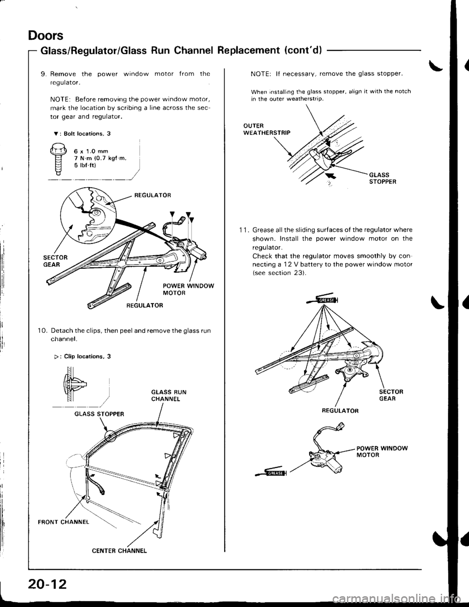
Doors
Glass/Regulator/Glass Run Channel Replacement (cont'd)
9. Remove the power window motor from the
regulator.
NOTE: Before removing the power window motor,
mark the location by scribing a line across the sec
tor gear and regulator.
V: Bolt locations, 3
Qp o"r.o--
El 7Nm(0.7ksf m.
Fl 5 lbf ftls?/:,/
Detach the clips, then peel and remove the glass run
cnanner.
> : Clip locations, 3
10.
GLASS STOPPER
FRONT CHANNEL
CENTEB CHANNEL
20-12
11.
NOTEr lf necessary, remove the glass stopper.
When installing the glass stopper, align it with the notch
in the outer weatherstrip.
Grease allthe sliding surlaces of the regulator where
shown. Install the power window motor on the
regulator.
Check that the regulator moves smoothly by con
necting a 12 V battery to the power window motor
(see section 23).
d
S*--.--;HERwrNDow
-Rt-/'
REGULATOR
Page 952 of 1680

Dashboard
Replacement Precautions
SRS wire harnesses are routed near the dashboard and
steenng column.
CAUTION:
a All SRS wire hsrnesses are covered wiih yellow insu-
lation. Before you disconnect any pan of an SRS wire
harness, disconnect the airbag conneclors.
a Whenever the ignition switch is ON (ll), or has been
tulned OFF for less than three minules, be careful not
to bump the SRS unit; the ai.bags could accidentally
deploy and cause damage or injuries.
a For additional precautions, refer lo the SRS sub-section
in section 23.
PASSENGER'S AIRBAG
Belore removing the dashboard:
1. Disconnect the battery negative cable, then discon-ne.r rhe n^.iriua.ahla
NOTEr The original radio has a coded thett protec,
tion circuit. Be sure to get the customer's code num
ber before- disconnecting the battery.- removing the No. 47 (7.5 A) fuse from the under-
hood tuse/relay box.- removing the radio.
After service, reconnect power to the radio and turn
it on. When the word "CODE" is displayed, enter
the customer's 5-digit code to restore radio
operation.
DRIVER'S AIRBAG
SRS UNIT
20-138
2.Install the short connectors (RED).
Driver's:
Remove the access panel, then disconnect the con-
nector between the cable reel and driver's airbag.
CABL€ REELCONNECTOR--_--._-_-----
Front passenger's:
Remove the glove box (see page 20-137), thendisconnect the connector between the front pas-
senger's airbag and SRS main harness.
FRONT PASSENGER'SAIRBAG CONNECTOR
SRS MAIN HARNESSCONNECTOR
ORIVER'S AIRBAG
Page 1014 of 1680
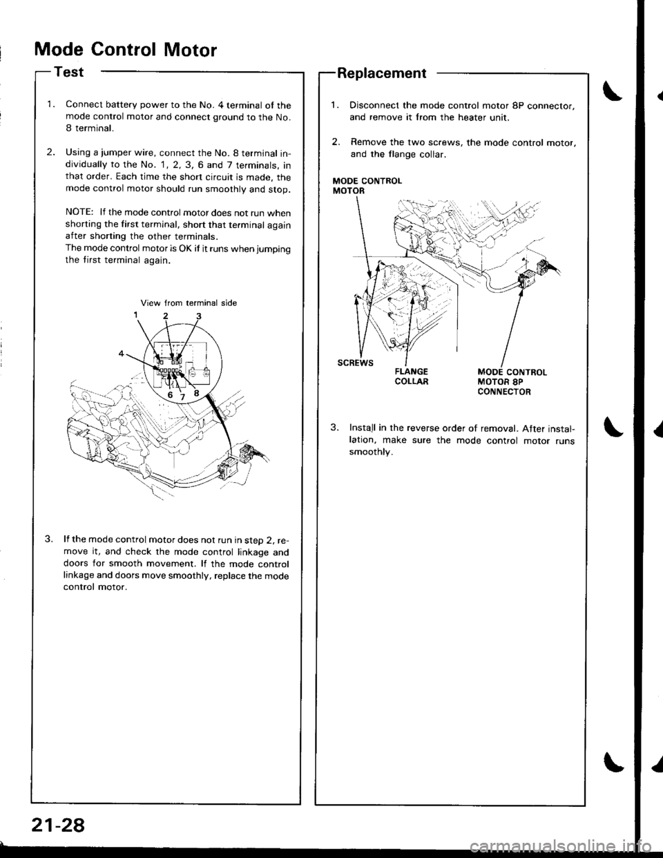
Mode Control Motor
Test
Connect battery power to the No. 4 terminal of themode control motor and connect ground to the No.
I terminal.
Using a jumper wire, connect the No. 8 termjnal in-dividually to the No. 1, 2, 3, 6 and 7 terminals, inthat order. Each time the short circuit is made. themode control motor should run smoothly and stop.
NOTE: lf the mode control motor does not run whenshorting the first terminal, short that te.minal againafter shorting the other terminals.
The mode control motor is OK if it runs when jumping
the tirst terminal again.
lf the mode control motor does nol run in steD 2, re-move it, and check the mode control linkage anddoors for smooth movement. lf the mode controllinkage and doors move smoothly, replace the mode
control motor.
Replacement
MODE CONTROLMOTOR
Disconnect the mode control motor 8P connector,
and remove it lrom the heater unit,
Remove the lwo sc.ews, the mode control motor,
and the flange collar.
MODE CONTROLMOTOR 8PCONNECTOR
Install in the reverse order of removal. After instal-lation, make sure the mode control motor runssmoothly.
21-28
Page 1015 of 1680
lli
''
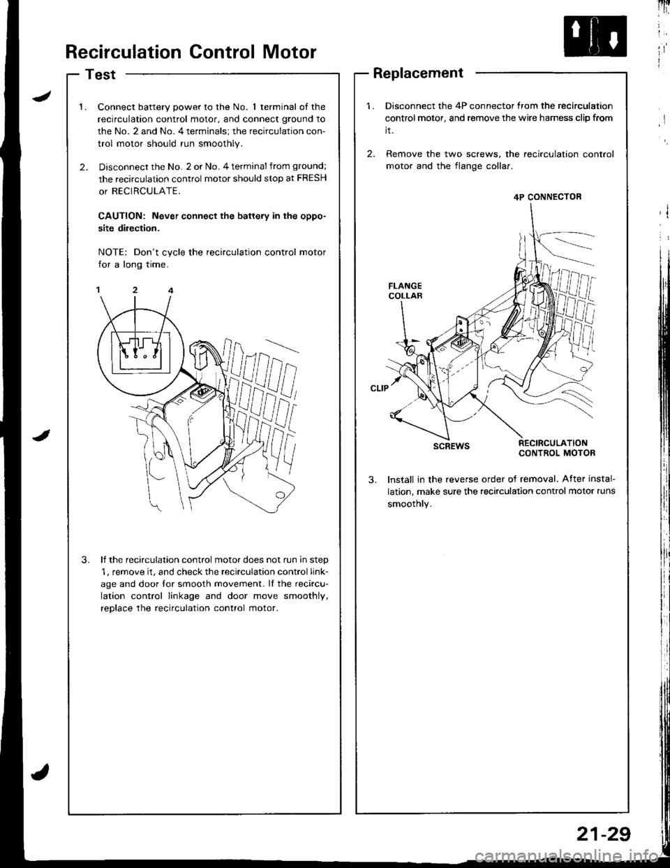
ltRecirculation Control Motor
Test
1.Connect battery power to the No. 1 terminal of the
recirculation control motor, and connect ground to
the No. 2 and No. 4 terminals; the recirculation con-
trol motor should run smoothly.
Disconnect the No. 2 or No. 4 terminal from ground;
the recirculation control motor should stop at FRESH
or RECIRCULATE.
CAUTION: Never connect the battery in the oppo-
site dilection.
NOTE: Don't cycle the recirculation control motor
for a long time.
lf the recirculation control motor does not run in step
1, remove it, and check the recirculation control link-
age and door lor smooth movement. If the recircu-
lation control linkage and door move smoothly,
reDlace the recirculation control motor.
3.
1.Disconnect the 4P connector from the recirculation
control motor, and remove the wire harness clip from
it.
2. Remove the two screws, the recirculation
motor and the flange collaf.
scREwsRECIRCULATIONCONTROL MOTOB
lnstall in the revefse order of removal. After instal-
lation, make sure the recirculation control motor runs
smoothly.
4P CONNECTOR
Replacement
21-29