Page 308 of 1680
This signals the ECM when the brake pedal is depressed
Inspeclion ot Brake Switch Signal.
Are the brake lights on withoutdepressing the brake pedal?
lnspect the HoRN STOP (20 Aifuse in the under-hood fuse/ relaybox,Do the brake lights come on?
Repair shori in the wire b€-
tween the brake switch and
the HoRN STOP {20 Al fuse.Replace tha HORN STOP (20 AlIus€.
Repair open in the wire be-tween the brtke switch andtho HORN STOP {20 Al tuse.
Inspect the brake switch {seesection 23).Check tor an open in the wire
{BKSW line):1- Depress the brake pedal.
2. Measure voltage between ECMconnector terminals D5 and Agwith the brake pedal depressed.
Repair open io th6 wiae batweonthe EcM lDs) rnd the brakeswitch.
Brake switch signal is OK.
ldle ControlSystem
Brake SwitchSignal
L
L
A {32P}LGl{BRN/BLX}
D {16P)
Wrre side of female terminals
I
Page 437 of 1680

. Ascending Control
When the TCM determines that the vehicle is climbing a hill in E position, the system extends the engagement area of
3rd gear to prevent the transmission from frequently shifting between 3rd and 4th gears, so the vehicle can run smooth
and have more power when needed,
NOTE:
Shift schedules between 3rd and 4th gear stored in the TCM enable the TCM'S fuzzy logic to automatically select themost suitable gear according to the magnitude of a gradient.
Fuzzy logic is a form of artificial intelligence that lets computers respond to changing conditions much like a human
mind would,
. Descending Control
When the TCM determines that the vehicle is going down a hill in E position, the shift-up speed from 3rd to 4th gear
when the throttle is closed becomes faster than the set speed for flat road driving to widen the 3rd gear driving area.This. in combination with engine braking from the deceleration lock-up, achieves smooth driving when the vehicle is
descending,
There are two descending modes with different 3rd gear driving areas according to the magnitude of a gradient stored in
the TCM.
When the vehicle js in 4th gear, and you are decelerating on a gradual hill, or when you are applying the brakes on a steephill, the transmission will downshift to 3rd gear. When you accelerate, the transmission will then return to 4th gear,
GRAOUAL ASCENOING MOOESHIFTING CHARACTERISTICSCONTROL
STEEP DESCENDING MODE
Vehicle Speed
. Deceleraiion Control
When the vehicle goes around a corner, and needs to decelerate first and then accelerate. the TCM sets the data for deceleration
control to reduce the number of times the transmission shifts. When the vehicle is decelerating from speeds above 30 mph(,18 km/h), the TCM shifts the transmission from 4th to 2nd earlierthan normal to cope with upcoming acceleration. (cont'd)
E
F
Km/h(mph)
14-21
Page 574 of 1680
Reverse ldler Gear
Installation
Fn"
14-158
\
\
Parking Brake Stop
I nspection/Adjustment
1.
2.
Set the parking brake lever in the E position.
N4easure the distance between the parking brake
pawl shaft and the parking brake lever roller pin as
shown.
STANDARD: 72.9-73.9 mm (2.87-2.91 in)
ROLI-ER PIN
PARKINGBRAKELEVEB
PARKING BRAKESTOPPARKING BRAKEPAWL SHAFT
It the measurement is out ol tolerance, select and
install the appropriate parl
table below.
3.
PARKING ERAKE
PARKING BRAKE STOP
Atter replacing the parking brake stop, make sure
the distance is within tolerance.
'z<"
lvleasuring
MarkPart Number
l24537-PA9-00311.00mm
(0.433 in)
11.00mm
{0.433 in)
224538 PAg -00310,80 mm
{0.425 in)
10.65 mm
{0.419 in)
324539-PA9 00310.60 mm(0.417 in)
10.30 mm(0.406 in)
1. Install the reverse idler gear.
2.Installthe reverse idler gear shalt holder and needle
bearing into the transmission housing, then tighten
the bolts.
6 x 1.0 mm12 N'm 11.2 kgl.m,8.7 tbf.tt)
\
Page 751 of 1680
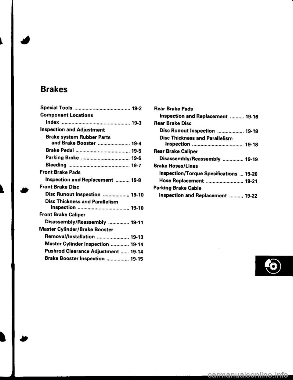
Brakes
Conventional Brakes ........ lg-1
Anti-lock Brake System (ABS) ............. 19-23
Page 752 of 1680

Brakes
Special Tools ............. 19-2
Component Locations
Index ................ ...... 19-3
Inspection and Adiustment
Brake system Rubber Parts
and Brake Booster ....................... 19-4
Brake Pedal ............ 19-5
Parking Brake ........ 19-6
Bleeding ................. t9-7
Front Brake Pads
Inspection and Replacement .......... l9-B
Front Brake Disc
Disc Runout Inspection ................... 19-10
Disc Thickness and Parallelism
Inspection .......... 19-10
Front Brake Caliper
Disassembly/Reassembly ............... l9-1 l
Master Cylinder/Brake Booster
Removal/1nsta|lation ....................... 19-13
Master Cylinder Inspection ............. 19-14
Pushrod Clearance Adjustment ...... 19-14
Brake Booster Inspection,.............,, lg-15
Rear Brake Pads
Inspeetion and Replacement .......... l9-16
Rear Brake Disc
Disc Runout Inspection ................... 1 g-18
Disc Thickness and Parallelism
Inspection .......... t9-18
Rear Brake Caliper
Disassembly/Reassembly ............... l9-19
Brake Hoses/Lines
Inspection/Torque Specifications ... l9-20
Hose Replacement ...................... ..... 19-21
Parking Brake Gable
f nspection and Replacement ,......,.,19-22
Page 754 of 1680
Component Locations
Index
FRONT BRAKESFront Brake Pads, page 19-8Front Brake Disc, page 19-10Front Brake Caliper, page 19-11
BLAKE HOSES/LINESInspection/Torque Specitications. page 19,20Hose Replacement, page 19-21
MASTER CYLINDEBR€moval/lnstallation, pag€ 19-'t3Mast€r Cylinder Inspection, page 19-14Pushrod Cl6aranc6 Adjustment, page 19-14BRAKE BOOSTERBrake Eoostor Inspoction, page 19-15Removal/lnstallation, pags'19-'13
BMKE PEDALlnspection andAdjustment, page 19-5
PARKING ERAKEAdjustment, page'19-6PARKING BRAKE CABLElnspoction and Roplacement, page 19-22
REAR DISC BRAKESRear Brake Pads, page 19-16Rear Brake Disc, page 19-18Rear Brake Caliper, page 19-19
19-3
Page 755 of 1680

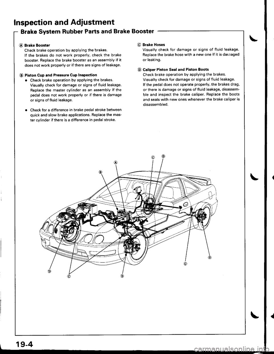
Inspection and Adiustment
Brake System Rubber Parts and Brake Booster
@ Brake Boost€r
Check brake operation by applying the brakes.
lf the brakes do not work properly, check the brake
booster. Replace the brake booster as an assembly if it
does not work properly or if there are signs of leakage
@ Piston cup and Pre3sure cup Inspection
. Check brake operation by applying the brakes.
Visually check for damage or signs of fluid leakage,
Replace the master cylinder as an assembly if the
pedal does not work properly or if there is damage
or signs of fluid leakage.
. Check for a difference in brake pedal stroke betlveen
quick and slow brake applications, Replace the mas-
ter cylinder if there is a difference in pedal stroke.
O Brake Hoses
Visually check for damage or signs of fluid leakage.
Replace the brake hose with a new one if it is darnaged
or leaking.
@ Caliper PBton Seal and Pkton Boots
Check brake operation by applying the brakes.
Visually check for damage or signs of fluid leakage.
lf the pedal does not operate properly, the brakes drag.
or there is damage or signs of fluid leakage, disassem-
ble and inspect the brake caliper. Replace the boots
and seals with new ones whenever the brake caliper is
disassembled.
19-4
Page 757 of 1680

Inspection and Adiustment
Parking Brake
Inspection
1. Pull the parking btake lever with 196 N
lbf) of force to Jully apply the parking
parking brake lever should be locked
soecified notches.
Lever Locked Notches: 6- l0
{20 kgf, 44
brake. The
within the
Pulled up with 196 N {2O kgf, 44 lbf)
LEVER LOCKED NOTCHES
2, Adjust the parking brake if the lever notches are out
of specification.
Adjustment
NOTE: After rear brake caliper servicing.loosen the park-
ing brake adjusting nut, start the engine, and depress the
brake pedal several times to set the self-adjusting brake
before adiusting the parking brake
1. Raise the rear wheels oIt the ground. and suppon
the car on safety stands.
!!@ ato"t the trort whoels bsfore jacking
up the roal ot tha car'
2. Make sure the parking brake arm on the rear brake
caliDer contacts the brake caliper pin.
19-6
8.
3. Pullthe parking brake lever up one notch'
Remove the rear console {see section 20)'
Tighten the adjusting nut until the rear wheels drag
slightly when turned.
7.
Release the parking brake lever fully, and check that
the rear wheels do not drag when turned. Readjust
if necessary.
Make sure the parking brakes are fully spplied when
the parking brake lever is pulled up fully.
Install the cap onto the parking brake cable end, and
reinstall the rear console.