Page 760 of 1680

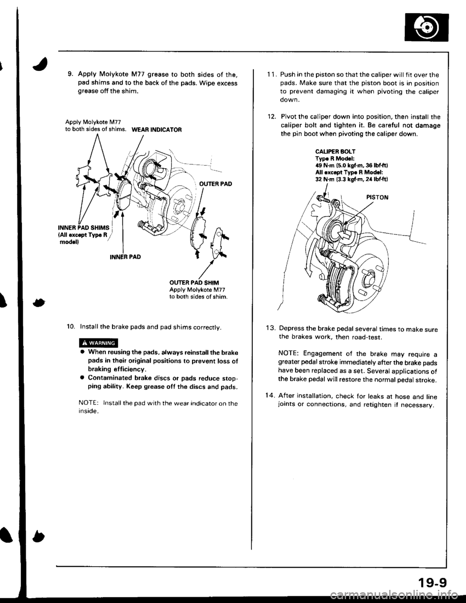
9. Apply Molykote M77 gresse to both sides of the,pad shims and to the back of the pads. Wipe excessgrease off the shim,
Apply N4olykote M77to both sides ot shims. WEAR |ND|CATOR
OUTER PAD
INN
\
ER,
OUTER PAD SHIMAppty Motykote M77to both sides of shim,
10. Install the brake pads and pad shims correctly.
a When reusing the pads, always reinstall the brakepads in their original positions to prevent loss of
braking etficiency.
a Contaminated btake discs ot pads reduce stop,ping ability. Keep grease oft the discs and pads.
NOTE: lnstall the pad wilh the wear indicator on theinside.
11.
14.
Push in the piston so that the caliper will fit over thepads. Make sure that the piston boot is in position
to prevent damaging it when pivoting the caliper
down.
Pivot the caliper down into position, then install the
caliper bolt and tighten it. Be careful not damage
the pin boot when pivoting the caliper down.
CAUPER AOLTTyp. R Mod.l:4!, N.m (5.0 kgl.m,36lbtft)All .xc.pt Typ. R Modcl:32 N.m 13.3 kgf.m,24 lbf.ftl
13.Depress the brake pedal several times to make surethe brakes work, then road-test.
NOTE: Engagement of the brake may require agreater pedal stroke immediately after the brake pads
have been replaced as a set. Several aDplications ofthe brake pedal will restore the normal pedal stroke.
After installation, check for leaks at hose and linejoints or connections, and retighten it necessary.
19-9
Page 768 of 1680

7.Clean the caliper thoroughly; remove any rust, and
check for grooves and cracks.
Check the brake disc for damage and cracks.
Make sure that the pad retainers are installed in the
correct positions.
PAD RETAINERS
Apply Molykote M77 to both sides of the shims and
to the back of the pads, Wipe excess grease off the
snrms.
Install the brake pads and pad shims on the caliper
bracket. Install the inner pad with its wear indicator
facing downward.
r When reusing the pads, always reinstall the
brake pads in their original positions to prsvent
loss of braking efficiency.
. Contaminated brake discs or pads reduce stop,ping ability. Keep grease off the discs and pads.
1 '�I.
INNER PAO SI{IM
lAll oxcopt Typo Rmod.ll
Apply Molykote[I77 grease toboth sides of thePADS shim.
Apply MolykoteM77 grease toboth sides of the
Rotate the caliper piston clockwise into place in the
cylinder, then align the cutout in the piston with the
tab on the inner pad by turning the piston back.
CAUTION: Lubricato th€ boot with rubbor grease
to avoid twisting the piston boot. lf the piston boot
is twist€d, back it out so it sits properly.
Install the brake caliper.
lnstall and tighten the caliper mounting bolts,
15. Installthe caliper shield.
CALIPER SHIELD
After installation, check for leaks at hose and linejoints or connections, and retighten if necessary.
Depress the brake pedal several times to make sure
the brakes work, then road-test.
NOTE: Engagement of the brake may .equire agreater pedal stroke immediately after the brake pads
have been replaced as a set. Several applications of
the brake pedal will restore the normal pedal stroke.
13.
14.
16.
't7.
19-17
Page 773 of 1680
Parking Brake Cable
Inspection and Replacement
CAUTION: Thc psrking brake cables must not be bent or distorted. This will lead to stiff operation and premature cable
lailure.
CLEVIS PIN
LOCK PIN
PARKING ERAKE LCVER
Check for smooth
EOUALIZER
(Sliding surface) PARKING BRAKEswtTcH
Disconnect the parking brake cable from the lever on the
caliper by removing the lock pin and clevis pin, and
remove the cable from the arm by removing the clip
PARKING BRAKE CABLE
CLEVIS PIN
CLIPReplace.
lSliding surlace)
19-22
Page 1391 of 1680

I
I
)
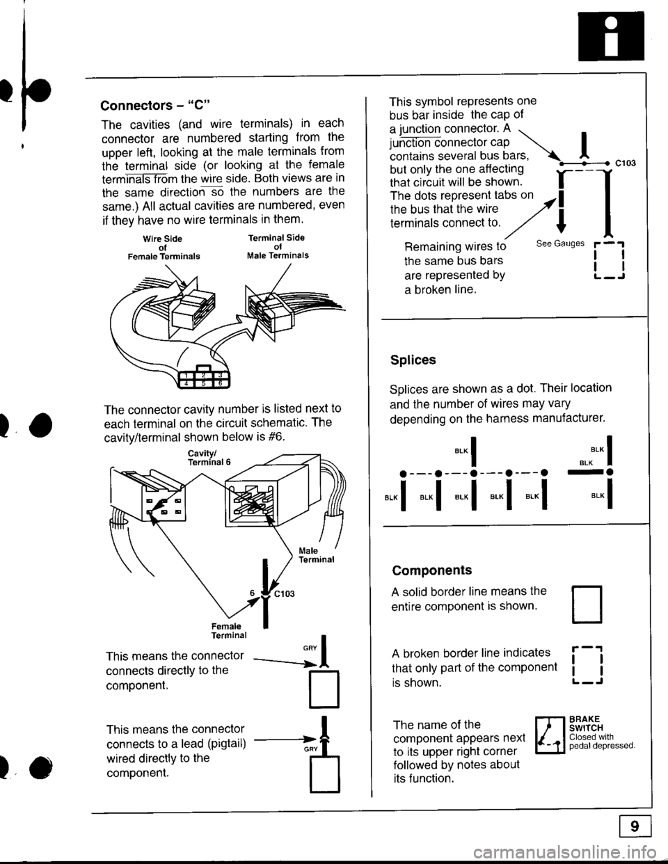
Connectors - "C"
The cavities (and wire terminals) in each
connector are numbered starting from the
upper left, looking at the male termlnals from
the terminal side (or looking at the female
termhaiSTiom the wire side. Both views are in
the same direction-so the numbers are the
same.) All actual cavities are numbered, even
if they have no wire terminals in them.
Wire SideolFemale Terminals
Terminal SideolMale Terminals
II
l
--a
)
The connector cavity number is listed next to
each terminal on the circuit schematic. The
cavitv/terminal shown below is #6.
FemaleTerminal
This means the connector
connecls directly to the
componenl.
This means the connector
connects to a lead (pigtail)
wired directly to the
component.
This symbol represents one
bus bar inside the cap of
a junction connector. A ...
Lrh.t'-=*nn".tor cap Icontains several bus bars, A
but only the one aflecting
that circuit will be shown. f-
--
The dots represent tabs on althe bus that the wire ,2il;;;;';;;;;;:;i;
/// I
Remaining wires to see Gauses
the same bus bars
are represented by
a broken line.
Splices
SDlices are shown as a dot. Their location
and the number of wires may vary
depending on the harness manuJacturer.
".^** I-o
*-l
c103
tl
l1
*-l
a --- a --- a --- a---a
*,,1 *"1 *-l *-l *-l
Components
A solid border line means the
entire component is shown.
A broken border line indicates
that only part of the component
rs snown.
ll
tl
The name of the
component appears nexl
to its upper right corner
followed by notes about
its f unction.
BRAKEswrTcHClosed withpedaldepressed.
Page 1416 of 1680
UNDER-HOODFUSE/RELAYBOX
FUSE 49DR rOC(SUNNOOF
FUSE 50RFo:FnostEF
FUSE 5I+a$ LL16A
FUSE 52HOR',|, STOP20AI
I
IJ
WHT/GFN
'13
?
WHT/GFNWHT/GRN
WHT/GFN
c4521'l(RS 10)
c440PHOfO 62
1 UNDER.I DASH
i FUSE/: RELAYI BOX
IPHOTO 58
J
WHT/GRN
==:==t- c418
i - -'00 |\,4odel
[ "ru, i
- _t - i
1
(cont'd)
Lc661
c662
WHl/GFNWHT/GFN
c563 12cseo i zc448
(Cruise 2)
o I caeo 'lc4311
ia---;,;"]
tlL------J
t1tl
BRAKEswtTcHPages 23-6('98-'39), 24,6 ( 00),34-1, 39 (98,'�99),39-4 (00),44,t 10 6, 110-7, 138('98-'99), and138-1 (00)PHOTQ 129
iF*,
-1-
MOONROOFRELAYPage 122
REARwtNoowDEFOGGERRELAYPage 64
HORN RELAYPage 40
L------JGAUGEASSEMBLYpage 80
coMBr.NATIONLIGHTSWITCHPage 100
HAZARDWARNINGswtTcHPage 110-2or 110'4
10-9
Page 1448 of 1680

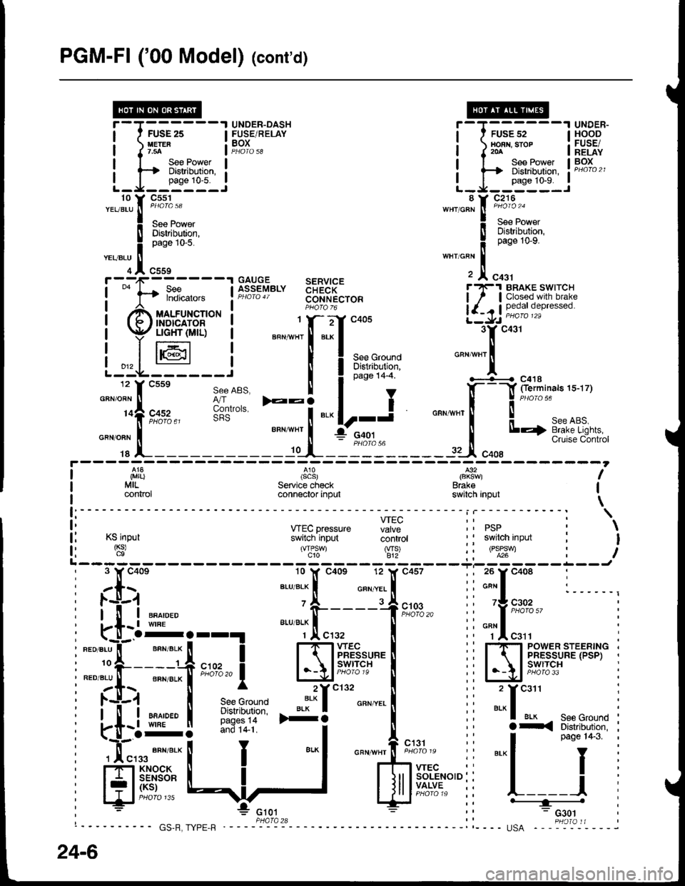
PGM-FI ('00 Model) lcont'd)
f ---,1-------1 GAITGE SERVICE
!
""
l-t fl?i*." lfr:?"'Y"'" 33FR[",o"I
| ""^,.,^
""r,o"t" t F;J$"
i Br,ffi*
-""'Ti"::"'""
'
F fl::"",.,, !f":?sy"'" $FR["r"" i7.l S[t5',"',1flJ,:1"
,ff uo.rrn"t'o* ! PHoro-6
!-r -/ ffi ore'"*"o
(f/ffirir,r$- I """-"11-"J** 3yc431
| p$tr6l:,- i *".;f:.:f
"oou ..-.t'';;;;" "
l-.L-@---i I Iar'u+t
'""*"'l
12 f csse see ABS. I I o"o" t+-+ '-+---{ c41s
"-"lt;;;"
t;dil
-:i
"."|r-i "".*[--f:il-.
iL_1
SeeABS. I t , .l(- -l fierminals 1s-17)
3o'.,", E:i
"." lr-j o"n,nn, ! J
"o'"'ur""or.
______-.f _t-_il":______rJ"oo,'*Bi""i'""*#i;
I ,i,1|}
I MrL.
I connor
(scs)Service checkconnector input
l€2
Brakeswitch inpul
I
I
\f:----- - - - - - i | - - - - - - - - - - - : \
ii *Ecpressure Hi: ii psp i \
l: Ksinput switch'input coritiot ' I swilch input : I
f l '$' 'T,'J S' ii oll:t : iL------- ------Ji 3 Y c40e 10 lf c40s 12 l( c457 ; ; 26 y c408 :, zls ar-uar-x I o"n.,.. I ii*"I :______,: l.-l-1 'A rJ
; l-'!r-i ""^,"." o-----+t;%," i" 'f ,"#!",,
: kt-l:orr!
"""*.[",.,
| :i "Tl"r" :
I ".o".u"il-' ""n".* [ I 1-1-1wec l� i rf, rsyr:sriF,.rB,]," i
i:."i:t--"# *n,,1 l-\l;tff#"'I ii IA'|5't'f3,i^'''*' i
i zt.\. [ ^ 2Yc132 [ ,' 2 Ycail :
I l.+.1 | see Grouno ':* I o"" ".. I i i ..- I :
i .-tiql i*}:11- *i
I",., ii
"'^f*il{:"{{i$l
i
i *'...#:t I
-"1 """'#*=:
ii
"'-l
pas€1+3
i
i
H** {:,]
'
$ff.':*'"ii l-=i
i
24-6
Page 1453 of 1680
FUSE 52HOBI|, STOP20A
c216
UNDER-HOODFUSE/RELAYBOXSee PowerDistribution,page 10-9.
See Powe.Distribution,page 10-9.
WHT/GRN
C'osed withl--f uiiiipna-a depressed.
c418(Termlnals 5-7)
WHT/GFN
-l -..1113i::l, ? #:f"*".u'o?I ",
REEL
SeeHOrns
4 Y c4s1BLU/GFN II.-l----
i ll ".u o"n ! 9EcuRIJY-SYSTEM Att except,, ?--1f.^ cooL.tNEcroR usA Rs
1**9 it*'.__;il__.
t=^----- STEERTNGag I WHEEL
diiiinlor- |SET/RESUME IswrrcH i
I
(cont'd)
c431BRAKEswtTcH
I '-l--P'�---e"
l L_ffi___-l3 Y c431 .9"-f------9*-t "or,-."1""L.------"0,,
i@ @ iF;5""
f-----Y (Terminals 1s-17) L--f.--------L-Jt I e/,o,o5, 1f ------4c2
o"n*",! $
'*""Tl----*irt.ouu
""'-
! seeABs. PGM-FI. 'f o [ilb'i5o'
I Brake Lghls. Automatic rr onr neo I r-r onr er-x I
. L _ _i:Tl1T:: - - - - - -- - -'-l- - - - - - - rI slr
i-#,[?=== input - input lPtroto.t
l'L------ ------J
34-1
Page 1486 of 1680
NOTE: Fuse 31 is HOT with lgnition Switch in START (lll) and clutch pedal depressed or A./T Gear Selector
in PARK (P) or NEUTRAL (N), see Starting System, pages 21 and 21-1.
See BrakeSystemlndicatorI i^ht
c504PHO|O 62
SBe Headlight
FUSE 31STAATEAS|GTAL7.54uee
Switch,page 100-'1. I
FUSE 30usrnu EtlTUGT'Tl|?.5A
S€e BrakoSystemlndicatorUqht
INTEGBATEDCONTROL UNITPHOfO 62
UNDER-OASHFUSE/RELAYBOX
SeeCeilingLight
c422
DRIVER'S DOORswtTcHClosed withdoor open.
PHoto 88 (sedan)
70-1