1998 ACURA INTEGRA brake booster
[x] Cancel search: brake boosterPage 45 of 1680

En gine Remova l/l nstal lation
(cont'dl
Remove the intake air duct, air cleaner housing
assembly and the bracket.
6 r 't.0 mm9.8 N.m (1.0 kgt.m, 7.2 lbf.ft)
Remove the evaporative emission {EVAP)
canister hose (B 18B1, B'18C1 eng;nes).
control
5-4
\
7. Remove the brake booster vacuum hose, evapora-
tive emission (EVAP) control canister hose and tuel
return hose (818C5 engine).
Remove the engine wire harness connectors on the
right side of engine compartment.
6 x 1.0 mm9.8 N.m l1.O kgl.m,
Page 79 of 1680

Gylinder Head
Removal (cont'dl
Remove the fuel return hose and positive crankcase
ventilation (PCV) hose.
Remove the brake booster vacuum hose, water
bypass hose and vacuum hose.
ltosE
VACUUM HOSE
6-18
10.
9.
11.
Remove the throttle cable,
Remove the throttle control cable (automatic trans-
mission only).
NOTE:
. Take care not to bend the cable when removing
it. Always replace any kinked cable with a new
one.
. Adjust the throttle cable and throttle control
cable when installing (s€e section 11 and 14).
THROTTLE CONTROLCABLE
ADJUSTING NUT
Remove the engine wire harness connectors and
wire harness clamps f.om the cylinder head and the
intake manifold.
Four fuel injector connectors
Intake air temperature (lATl sensor connector
Engine coolant temperature {ECT) sensor con,
nector
TDC/CKP/CYP sensor connector
lgnition coil connector
ECT gauge sending unit connector
Throttle position (TP) sensor connector
Manifold absolute pressure (MAP) sensor con-
necto r
ldle air control (lAC) valve connector
EVAP purge control solenoid valve connector
Crankshaft speed fluctuation (CKF) sensor con-
nector
a
a
a
a
a
a
a
a
ADJUSTING
Page 752 of 1680

Brakes
Special Tools ............. 19-2
Component Locations
Index ................ ...... 19-3
Inspection and Adiustment
Brake system Rubber Parts
and Brake Booster ....................... 19-4
Brake Pedal ............ 19-5
Parking Brake ........ 19-6
Bleeding ................. t9-7
Front Brake Pads
Inspection and Replacement .......... l9-B
Front Brake Disc
Disc Runout Inspection ................... 19-10
Disc Thickness and Parallelism
Inspection .......... 19-10
Front Brake Caliper
Disassembly/Reassembly ............... l9-1 l
Master Cylinder/Brake Booster
Removal/1nsta|lation ....................... 19-13
Master Cylinder Inspection ............. 19-14
Pushrod Clearance Adjustment ...... 19-14
Brake Booster Inspection,.............,, lg-15
Rear Brake Pads
Inspeetion and Replacement .......... l9-16
Rear Brake Disc
Disc Runout Inspection ................... 1 g-18
Disc Thickness and Parallelism
Inspection .......... t9-18
Rear Brake Caliper
Disassembly/Reassembly ............... l9-19
Brake Hoses/Lines
Inspection/Torque Specifications ... l9-20
Hose Replacement ...................... ..... 19-21
Parking Brake Gable
f nspection and Replacement ,......,.,19-22
Page 754 of 1680

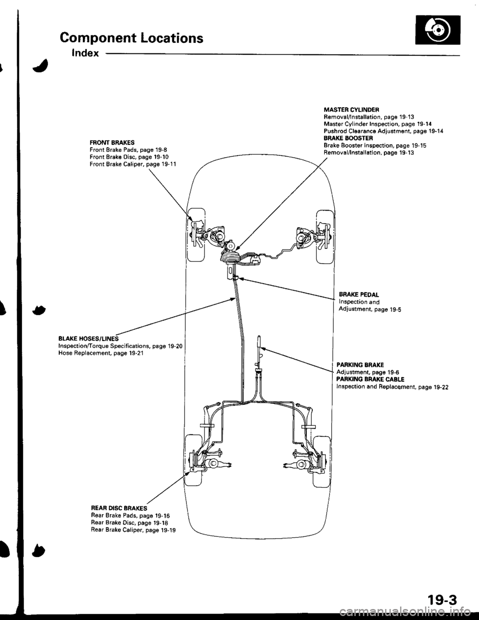
Component Locations
Index
FRONT BRAKESFront Brake Pads, page 19-8Front Brake Disc, page 19-10Front Brake Caliper, page 19-11
BLAKE HOSES/LINESInspection/Torque Specitications. page 19,20Hose Replacement, page 19-21
MASTER CYLINDEBR€moval/lnstallation, pag€ 19-'t3Mast€r Cylinder Inspection, page 19-14Pushrod Cl6aranc6 Adjustment, page 19-14BRAKE BOOSTERBrake Eoostor Inspoction, page 19-15Removal/lnstallation, pags'19-'13
BMKE PEDALlnspection andAdjustment, page 19-5
PARKING ERAKEAdjustment, page'19-6PARKING BRAKE CABLElnspoction and Roplacement, page 19-22
REAR DISC BRAKESRear Brake Pads, page 19-16Rear Brake Disc, page 19-18Rear Brake Caliper, page 19-19
19-3
Page 755 of 1680

Inspection and Adiustment
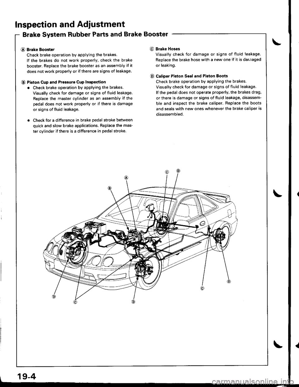
Brake System Rubber Parts and Brake Booster
@ Brake Boost€r
Check brake operation by applying the brakes.
lf the brakes do not work properly, check the brake
booster. Replace the brake booster as an assembly if it
does not work properly or if there are signs of leakage
@ Piston cup and Pre3sure cup Inspection
. Check brake operation by applying the brakes.
Visually check for damage or signs of fluid leakage,
Replace the master cylinder as an assembly if the
pedal does not work properly or if there is damage
or signs of fluid leakage.
. Check for a difference in brake pedal stroke betlveen
quick and slow brake applications, Replace the mas-
ter cylinder if there is a difference in pedal stroke.
O Brake Hoses
Visually check for damage or signs of fluid leakage.
Replace the brake hose with a new one if it is darnaged
or leaking.
@ Caliper PBton Seal and Pkton Boots
Check brake operation by applying the brakes.
Visually check for damage or signs of fluid leakage.
lf the pedal does not operate properly, the brakes drag.
or there is damage or signs of fluid leakage, disassem-
ble and inspect the brake caliper. Replace the boots
and seals with new ones whenever the brake caliper is
disassembled.
19-4
Page 764 of 1680

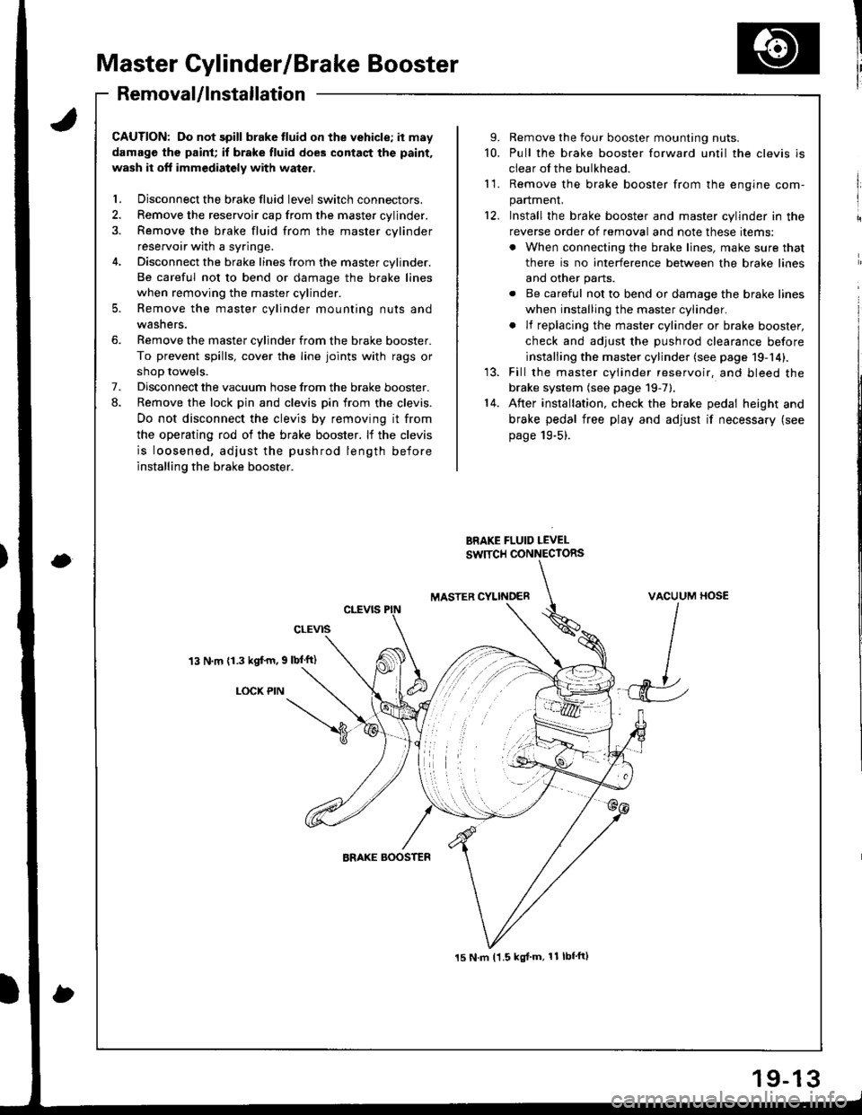
Master Cylinder/Brake Booster
I'RemovaUlnstallation
CAUTION: Do not spill brake tluid on the vehicle; it may
damage the paint; if brake fluid does contact the paint,
wash it oft immediatoly with water.
l. Disconnect the brake fluid level switch connectors.
2. Remove the reservoir cap from the master cylinder.
3. Remove the brake fluid from the master cvlinder
reservoir with a syringe.
4. Disconnect the brake lines from the master cylinder.
Be careful not to bend or damage the brake lines
when removing the master cylinder.
5. Remove the master cylinder mounting nuts and
washers.
6. Remove the master cylinder from the brake booster.
To prevent spills, cover the line joints with rags or
shoD towels.
7. Disconnect the vacuum hose from the brake booster.
8. Remove the lock pin and clevis pin from the clevis.
Do not disconnect the clevis by removing it from
the operating rod of the brake booster. lf the clevis
is loosened, adjust the pushrod length before
installing the brake booster.
13 N.m (1.3 kgf'm, 9 lbl'ft)
LOCX PIN
9. Remove the four booster mounting nuts.
10. Pull the brake booster forward until the clevis is
clear of the bulkhead.
11. Remove the brake booster from the enqine com-
panmenL
12, Install the brake booster and master cylinder in the
reverse order of removal and note these items:
. When connecting the brake lines, make sure that
there is no interference between the brake lines
and other parts.
. Be careful not to bend or damage the brake lines
when installing the master cylinder.
. lf replacing the master cylinder or brake booster,
check and adiust the DUshrod clearance before
installing the master cylinder (see page 19-14).
13. Fill the master cylinder reservoir, and bleed the
brake system (see page 19-7).'14. After installation, check the brake pedal height and
brake pedal free play and adjust if necessary (see
page 19-5).
BRAKE FLUID LEVEL
SW]TCH CONNECTORS
MASTER CYLINOERVACUUM HOSE
J
15 N.m t1.5 kgl'm, 11 lbf'ft)
Page 765 of 1680

Master Cylinder/Brake Booster
Master Cylinder InspectionPushrod Clearance Adjustment
NOTE: Master cylinder pushrod'to piston clearance must
be checked and adjustments made, if necessary, before
installing master cylinder.
1. Set the special tool on the master cylinder body;
push in the center shaft until the top of it contacts the
end of the socondary piston by turning the adjusting
nut.PUS'IROD ADJUSTTTiENT GAUGE07JAG - SDiOl(xl
SECOITDARYPISTON
CEl{IERSHAFT
MASTER CYLINDER
Without disturbing the center shaft's position,
the soecial tool upside down on the booster.
3. Install the master cylinder nuts and tighten to the
sDecified toroue.
4. Connect the booster inline with a vacuum gauge 0 -
101 kPa {0 - 760 mmHg, 30 in.Hg) to the booster's
engine vacuum supply, and maintain an engine
speed that will deliver 66 kPa (500 mmHg, 20 in.Hg)
vacuum.
5. With a feeler gauge, measure the clearance between
the gauge body and the adjusting nut as shown.
Clsarance: 0 - 0,i[ mm (0 - 0.02 inl
VACUUM GAUGElCommelcially availabl€|0 - 101 kPal0 - 760 mm H9,30 in.Hgl
AINUSTING NUT
BRAKEBOOSTEB
MAS'ER CYLINDER NUT15 N.m ll.5 kgf.m. 11 lbl.ftl
CAUTION:
. Do not spill blake fluid on the vohicle; it may damago
th6 paint; if brake fluid does contast ths paint, wash
it off immsdiately with water.
. Before reassembling. chock that all parts are tree of
dust and othor toreign particlgs,
. Do not trv to dissssemblo the master cylinder
assembly. Replace the mast€r cylinder assembly
with s new part if nocossary.
. Make sure no dirt or othor toroign matter is allowed
to contaminate th€ brako fluid.
RESERVOIR SEALCheck for damage and
deterioration.
ROD SEALCheck for damageand deterioration.
AIIUSNNG NUT
19-14
FEELER GAUGE
Page 766 of 1680

1.
8.
NOTE: lf the clearance between the gauge body
and adjusting nut is 0.4 mm (0.02 in), the pushrod-
to-piston clearance is 0 mm. However, if the clear-
ance between the gauge body and adjusting nut is
0 mm, the pushrod-to-piston clearance is 0.4 mm(0.02 in) or more. Therefore it must be adjusted and
rechecked.
lf clearance is incorrect, loosen the star locknut and
turn the adjuster in or out to adjust.
NOTE:
. Adjust the clearance while the specified vacuum
is applied to the booster.
. Hold the clevis while adjusting.
Tighten the star Iocknut securely.
Remove the special tool.
0 - o.il mm l0 - 0.02 inl
Brake Booster Inspection
Functions Tgst
1. With the engine stopped, depress the brake pedal
several times to deplete the vacuum reservoir, then
depress the pedal hard and hold it for 15 seconds. ll
the pedal sinks, either the master cylinder is
bypassing internally; or the brake system (master
cylinder, lines, modulator proportioning valve, orcaliper) are leaking.
Start the engine with the pedal depressed. lf thepedal sinks slightly, the vacuum booster is operat-
ing normally. lf the pedal height does not vary, the
booster or check valve is faulty.
With the engine running, depress the brake pedal
lightly. Apply just enough pressure to hold back
automatic transmission creep, lf the brake pedal
sinks more than 25 mm (1.0 in.) in three minutes,
the master cylinder is faulty. A slight change inpedal height when the A,,/C compressor cycles on
and off is normal. (The A/C compressor load
changes the vacuum available to the booster.)
Leak Test
1. Depress the brake pedal with the engine running,
then stop the engine. lf the pedal height does not
vary while depressed for 30 seconds, the vacuum
booster is OK. lf the pedal rises, the booster is
fau lty.
2. With the engine stopped, depress the brake pedal
several times using normal pressure. When thepedal is first depressed, it should be low. On con-
secutive applications, the pedal height should grad-
ually rise. lf the pedal position does not vary, check
the booster check valve.
Boostor Ch€ck Valve T6st
1. Disconnect the brake booster vacuum hose at the
booster,
Start the engine and let it idle. There should be vac-
uum available. It no vacuum is available. the check
valve is not working properly. Replace the brake
booster vacuum hose and check valve, and retest.
VACUUM HOSE(Check valve built-in)
STAR LOCKNUT22 t{.m12.2 ksl.m, 16lbf.ftl
cLEVtS
ADJUSTER
ADJUSTMENT GAUGE07JAG - SD40t00
9. Adjust the pushrod length as shown if the booster
is removed.
1161 0.5 mm14.61 0.02 inl
PUSHRODLOCKNUT15 N m 11.5 kgf m, 11 lbf'ftl
10. Instali the master cylinder.