Page 576 of 1807

DI-161
389 Author�: Date�:
1997 SUPRA (RM502U)
DTC CHART (Manufacture Controlled)
DTC No.
(See Page)Detection ItemTrouble AreaMIL*Memory
P1100
(DI-247)Barometric Pressu")
- DIAGNOSTICSENGINE (2JZ-GTE)
DI-161
389 Author�: Date�:
1997 SUPRA (RM502U)
DTC CHART (Manufacture Controlled)
DTC No.
(See Page)Detection ItemTrouble AreaMIL*Memory
P1100
(DI-247)Barometric Pressure Sensor Cir-
cuit MAlfunction�ECM��
P1200
(DI-248)Fuel Pump Relay / ECU Circuit
Malfunction
�Open or short in fuel pump ECU circuit
�Fuel pump ECU
�ECM power source circuit
�Fuel pump
�ECM
-�
P1300
(DI-252)Igniter Circuit
Malfunction�Open or short in IGF or IGT circuit from igniter to ECM
�Igniter
�ECM
��
P1335
(DI-257)Crankshaft Position Sensor
Circuit Malfunction (during
engine running)
�Open or short in crankshaft position sensor circuit for NE sig-
nal
�Crankshaft position sensor for NE signal
�Starter
�ECM
-�
P1400
(DI-258)Sub Throttle Position Sensor
Malfunction�Open or short in sub throttle position sensor circuit
�Sub throttle position sensor
�ECM
��
P1401
(DI-261)Sub Throttle Position Sensor
Range / Performance Problem�Sub throttle position sensor��
P1405
(DI-262)Turbo Pressure Sensor Circuit
Malfunction�Open or short in turbo pressure sensor circuit
�Turbo pressure sensor
�ECM
��
P1406
(DI-265)Turbo Pressure Sensor Circuit
Range / Performance Problem�Turbo pressure sensor��
P1511
(DI-266)Boost Pressure Low
Malfunction
�Air intake (leakage or clogging)
�Actuator (for waste gate valve, IACV control valve, exhaust
bypass valve and exhaust gas control valve)
�Short in VSV for waste gate valve, IACV control valve, exhaust
bypass valve and exhaust gas control valve circuit
�ECM
��
P1512
(DI-274)Boost Pressure High
Malfunction
�Actuator (for waste gate valve and exhaust bypass valve)
�Short in VSV for waste gate valve and exhaust bypass valve
circuit
�ECM
��
P1520
(DI-279)Stop Light Switch Signal
Malfunction�Short in stop light switch signal circuit
�Stop light switch
�ECM
��
P1600
(DI-282)ECM BATT
Malfunction�Open in back up power source circuit
�ECM��
*: � .... MIL dose not light up
� ... MIL lights up
Page 584 of 1807

DI-169
397 Author�: Date�:
1997 SUPRA (RM502U)
PROBLEM SYMPTOMS TABLE
When the malfunction code is not confirmed in the DTC check and the problem still can not")
DI4SL-01
- DIAGNOSTICSENGINE (2JZ-GTE)
DI-169
397 Author�: Date�:
1997 SUPRA (RM502U)
PROBLEM SYMPTOMS TABLE
When the malfunction code is not confirmed in the DTC check and the problem still can not be confirmed
in the basic inspection, then proceed to this step and perform troubleshooting according to the numbered
order given in the table below.
SymptomSuspect AreaSee page
Does not start (Engine does not crank)1. Starter and Starter relayST-14, ST-16
Does not start (No initial combustion)
1. ECM power source circuit
2. Fuel pump control circuit
3. Engine control module (ECM)DI-304
DI-248
IN-18
Does not start (No complete combustion)1. Fuel pump control circuitDI-248
Difficult to start (Engine cranks normally)
1. Starter signal circuit
2. Fuel pump control circuit
3. CompressionDI-301
DI-248
EM-3
Difficult to start (Cold engine)1. Starter signal circuit
2.Fuel pump control circuitDI-301
DI-248
Difficult to start (Hot engine)
1. Starter signal circuit
2. Fuel pressure control circuit
3. Fuel pump control circuitDI-301
DI-309
DI-248
Poor idling (High engine idle speed)1. A/C signal circuit
2. ECM power source circuitDI-722
DI-304
Poor idling (Low engine idle speed)1. A/C signal circuit
2. Fuel pump control circuitDI-722
DI-248
Poor idling (Rough idling)1. Compression
2. Fuel pump control circuitEM-3
DI-248
Poor idling (Hunting)1. ECM power source circuit
2. Fuel pump control circuitDI-304
DI-248
Poor Driveability (Hesitation/Poor acceleration)1. Fuel pump control circuit
2. A/T faultyDI-248
DI-391
Poor Driveability (Surging)1. Fuel pump control circuitDI-248
Engine stall (Soon after starting)1. Fuel pump control circuitDI-248
Engine stall (During A/C operation)1. A/C signal circuit
2. Engine control module (ECM)DI-722
IN-18
Page 586 of 1807
FI6930
B-W
R/B No.22
2A
EFI No.1 B
BatteryEFI Main RelayB-R R/B No.2
B-Y
W-B
EBEA2
2
22
2 23
5
1
EA1
8
5
1
Mass Air Flow Meter2
5Y-R
B-RA
B
B 66
28
E2G
E1 VG GR24
M-RELB+ ECM
1
- DIAGNOSTICSENGINE (2JZ-GTE)
DI-171
399 Author�: Date�:
1997 SUPRA (RM502U)
WIRING DIAGRAM
INSPECTION PROCEDURE
1 Connect the OBD II scan tool or TOYOTA hand-held tester, and read value of
mass air flow rate.
RESULT:
(a) Connect the OBD II scan tool or TOYOTA hand-held tester to the DLC3.
(b) Turn ignition switch ON and push the OBD II scan tool or TOYOTA hand-held tester main switch ON.
(c) Start the engine.
CHECK:
Read mass air flow rate on the OBD II scan tool or TOYOTA hand-held tester.
RESULT:
Type IType II
Mass air flow rate0.0 gm / sec.359.0 gm / sec. or more
Type I Go to step 2.
Type II Go to step 5.
Page 587 of 1807
BE6653
P24310A00099
ON
1(+)
A00689
STARTCheck Harness A
ECM
B66 VG(+)
DI-172
- DIAGNOSTICSENGINE (2JZ-GTE)
400 Author�: Date�:
1997 SUPRA (RM502U)
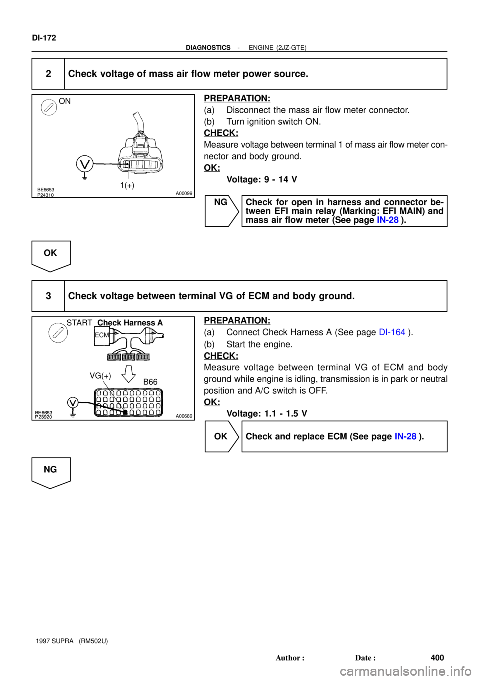
2 Check voltage of mass air flow meter power source.
PREPARATION:
(a) Disconnect the mass air flow meter connector.
(b) Turn ignition switch ON.
CHECK:
Measure voltage between terminal 1 of mass air flow meter con-
nector and body ground.
OK:
Voltage: 9 - 14 V
NG Check for open in harness and connector be-
tween EFI main relay (Marking: EFI MAIN) and
mass air flow meter (See page IN-28).
OK
3 Check voltage between terminal VG of ECM and body ground.
PREPARATION:
(a) Connect Check Harness A (See page DI-164).
(b) Start the engine.
CHECK:
Measure voltage between terminal VG of ECM and body
ground while engine is idling, transmission is in park or neutral
position and A/C switch is OFF.
OK:
Voltage: 1.1 - 1.5 V
OK Check and replace ECM (See page IN-28).
NG
Page 606 of 1807

B
B
B
EA2
B-R B-R")
S02435
Battery
B
W-BEFI No.1
R/B No.2R/B No.2
EFI Main Relay
2
2A 1
B-W
2 22
2
1
2 3 5B-YB-R
8
EA1
B-REA25
B-RGR
W24
48A
BM-REL
OX1
23
1 4
B-L Heated Oxygen
Sensor
(Bank 1 Sensor 1)
B
B
B
EA2
B-R B-R
B-R B-R
R-L
IJ1
IC1
2
4 20
23
1 4 Heated
Oxygen
Sensor
(Bank 1
Sensor 2)
IC1
20
IC1
IJ2
IC1
IJ1
BRBR
BR
BR-WBR-W
8
18 12R-L 9
IJ2
BR
BR-W5 R-L1471
41
72ECM
B+
E1
HT1
E01
OXS
E1
HTS
E01
EDEBBR
- DIAGNOSTICSENGINE (2JZ-GTE)
DI-191
419 Author�: Date�:
1997 SUPRA (RM502U)
WIRING DIAGRAM
INSPECTION PROCEDURE
1 Connect the OBD II scan tool or TOYOTA hand-held tester and read value for
voltage output of heated oxygen sensor.
PREPARATION:
(a) Connect the OBD II scan tool or TOYOTA hand-held tester to the DLC 3.
(b) Warm up engine to normal operation temperature.
CHECK:
Read voltage output of heated oxygen sensor (bank 1 sensor 1) when engine is suddenly raced.
HINT:
Perform quick racing to 4,000 rpm 3 times using accelerator pedal.
OK:
Both heated oxygen sensors (bank 1 sensor 1) output a RICH signal (0.45 V or more) at least
once.
OK Check and replace ECM (See page IN-28).
NG
Page 613 of 1807
DI-198
- DIAGNOSTICSENGINE (2JZ-GTE)
426 Author�: Date�:
1997 SUPRA (RM502U)
2 Check resistance of heated oxygen sensor heater (See page SF-82).
NG Replace heated oxygen sensor.
OK
Check and repair harness or connector be-
tween EFI main relay (Making: EFI MAIN) and
heated oxygen sensor and ECM.
Page 630 of 1807

FI6975
Throttle ValveVSVECM
EGR Valve
EGR Gas
Temp. Sensor
Exhaust Gas
Air
Intake
ChamberEGR
Vacuum
Modulator
S01078
R/B No.2
Battery R/B No.2
B
B-W
W-B EFI No.1
1
2A2 2
2 2 2
3
2 1
5
EFI Main Relay
B-Y B-R2
8
EA2
EA1VSV For EGR1
2 B-R P
GR
EGR Gas
Temp. Sensor
2
1BR-Y
W-BECM
75
24
46
65B
B
B
BEGR
E01
+B
M-REL
5V
THG
E2
EB
- DIAGNOSTICSENGINE (2JZ-GTE)
DI-217
445 Author�: Date�:
1997 SUPRA (RM502U)
DTC P0401 Exhaust Gas Recirculation Flow Insufficient
Detected
CIRCUIT DESCRIPTION
The EGR system recirculates exhaust gas, which is controlled to the proper quantity to suit the driving condi-
tions, into the intake air mixture to slow down combustion, reduce the combustion temperature and reduce
NOx emissions. The amount of EGR is regulated by the EGR vacuum modulator according to the engine
load.
If even one of the following conditions is fulfilled, the VSV is
turned ON by a signal from the ECM. This results in atmospher-
ic air acting on the EGR valve, closing the EGR valve and shut-
ting off the exhaust gas (EGR cut-off).
Under the following conditions, EGR is cut to maintain driveabil-
ity.
�Before the engine is warmed up.
�During deceleration (throttle valve closed).
�Light engine load (amount of intake air very small).
�Engine racing.
DTC No.DTC Detecting ConditionTrouble Area
P0401
After the engne is warmed up and run at 80 km/h (50 mph) for
3 to 5 min., the EGR gas temperature sensor value does not
exceed 45°C (113°F) above the ambient air temperature
(2 trip detection logic)�EGR valve stuck closed
�Short in VSV circuit for EGR
�Open in EGR gas temp. sensor circuit
�EGR hose disconnected
�ECM
WIRING DIAGRAM
DI4T3-01
Page 647 of 1807

S05422
To Turbo
Charcoal
Canister
Fuel Tank
ECMIntake Manifold VSV for
EVAP
S01079
Battery
EB
W-B
BB-W
R/B No.2
EFI No.1
EFI Main Relay
2 2A
2
2 2
2
35
1 2
B-R
B-YB-REA22VSV for EVAP
1274
B
ECM
EVAP
E01
B+
GR24
A
M-REL
V
EA18 1 DI-234
- DIAGNOSTICSENGINE (2JZ-GTE)
462 Author�: Date�:
1997 SUPRA (RM502U)
DTC P0441 Evaporative Emission Control System
Incorrect Purge Flow
CIRCUIT DESCRIPTION
To reduce HC emissions, evaporated fuel from the fuel tank is routed through the charcoal canister to the
intake manifold for combustion in the cylinders.
The ECM changes the duty signal to the VSV for EVAP so that the intake quantity of HC emissions is ap-
propriate for the driving conditions (engine load, engine speed, etc.) after the engine is warme up.
DTC No.DTC Detecting ConditionTrouble Area
P0441
The proper response to the computer command does not oc-
cur
(2 trip detection logic)
�Open or short in VSV circuit for EVAP
�VSV for EVAP
�Vacuum hose blocked or disconnected
�ECM
�Charcoal canister
WIRING DIAGRAM
DI4T6-01