Page 185 of 1807
Z07379
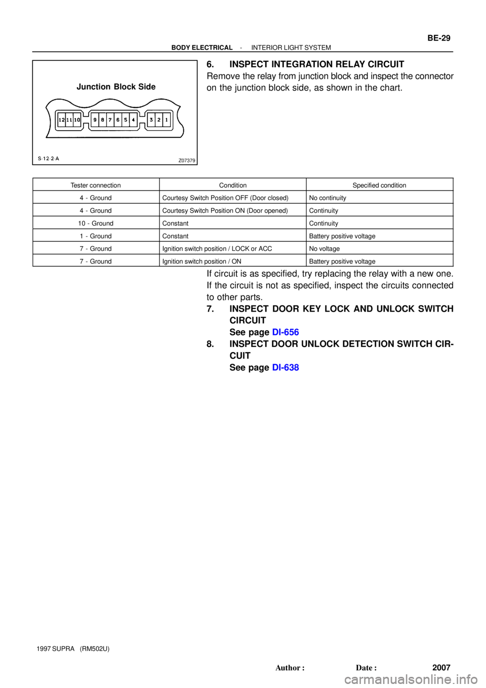
Junction Block Side
- BODY ELECTRICALINTERIOR LIGHT SYSTEM
BE-29
2007 Author�: Date�:
1997 SUPRA (RM502U)
6. INSPECT INTEGRATION RELAY CIRCUIT
Remove the relay from junction block and inspect the connector
on the junction block side, as shown in the chart.
Tester connectionConditionSpecified condition
4 - GroundCourtesy Switch Position OFF (Door closed)No continuity
4 - GroundCourtesy Switch Position ON (Door opened)Continuity
10 - GroundConstantContinuity
1 - GroundConstantBattery positive voltage
7 - GroundIgnition switch position / LOCK or ACCNo voltage
7 - GroundIgnition switch position / ONBattery positive voltage
If circuit is as specified, try replacing the relay with a new one.
If the circuit is not as specified, inspect the circuits connected
to other parts.
7. INSPECT DOOR KEY LOCK AND UNLOCK SWITCH
CIRCUIT
See page DI-656
8. INSPECT DOOR UNLOCK DETECTION SWITCH CIR-
CUIT
See page DI-638
Page 190 of 1807
Z18229
Front Wiper MotorCombination Switch
Wiper and Washer Switch
Washer Motor
Rear Wiper Motor and RelayWIPER Fuse J/B No.1
� �
BE0E5-01
BE-34
- BODY ELECTRICALWIPER AND WASHER SYSTEM
2012 Author�: Date�:
1997 SUPRA (RM502U)
WIPER AND WASHER SYSTEM
LOCATION
Page 193 of 1807

5. Low Speed:
INSPECT FRONT WIPER MOTOR OPERATION
Co")
N07801
31
N07802
21
N07803
3
1
N07804
61
5 3
N03983
1 3
- BODY ELECTRICALWIPER AND WASHER SYSTEM
BE-37
2015 Author�: Date�:
1997 SUPRA (RM502U)
5. Low Speed:
INSPECT FRONT WIPER MOTOR OPERATION
Connect the positive (+) lead from the battery to terminal 3 and
the negative (-) lead to terminal 1, check that the motor oper-
ates at low speed.
If operation is not as specified, replace the motor.
6. High Speed:
INSPECT FRONT WIPER MOTOR OPERATION
Connect the positive (+) lead from the battery to terminal 2 and
the negative (-) lead to terminal 1, check that the motor oper-
ates at high speed.
If operation is not as specified, replace the motor.
7. Stopping at Stop Position:
INSPECT FRONT WIPER MOTOR OPERATION
(a) Operate the motor at low speed and stop the motor opera-
tion anywhere by disconnecting positive (+) lead from ter-
minal 3.
(b) Connect terminals 3 and 5.
(c) Connect the positive (+) lead from the battery to terminal
6 and negative (-) lead to terminal 1, check that the motor
stops running at the stop position after the motor operates
again.
If operation is not as specified, replace the motor.
8. INSPECT REAR WIPER MOTOR AND RELAY OPERA-
TION
(a) Connect the positive (+) lead from the battery to terminal
1, and the negative (-) lead to terminal 3 and the motor
body, check that the motor operates.
Page 194 of 1807

(b) Disconnect the negative (-) lead from terminal 3, check
that the motor stop")
N03984
N03985
BE4118
BE4119
BE-38
- BODY ELECTRICALWIPER AND WASHER SYSTEM
2016 Author�: Date�:
1997 SUPRA (RM502U)
(b) Disconnect the negative (-) lead from terminal 3, check
that the motor stops running at the stop position.
If operation is not as specified, replace the motor and relay.
9. INSPECT INTERMITTENT OPERATION
Connect the positive (+) lead from the battery to terminal 1, and
the negative (-) lead to terminal 2 and the motor body, check
that the motor operates intermittently for 9 - 15 seconds.
If operation is not as specified, replace the motor and relay.
10. Front Washer:
INSPECT WASHER MOTOR OPERATION
Connect the positive (+) lead from the battery to terminal 2 and
the negative (-) lead to terminal 1, check that the motor oper-
ates.
NOTICE:
These tests must be performed quickly (within 20 seconds)
to prevent the coil from burning out.
If operation is not as specified, replace the motor.
11. Rear Washer:
INSPECT WASHER MOTOR OPERATION
Connect the positive (+) lead from the battery to terminal 2 and
the negative (-) lead to terminal 3, check that the motor oper-
ates.
NOTICE:
These tests must be performed quickly (within 20 seconds)
to prevent the coil from burning out.
If operation is not as specified, replace the motor.
Page 195 of 1807
Z18230
Brake Fluid Level Warning Switch
Parking Brake Switch
Telltale Light LH
Telltale Light RHVehicle Speed Sensor
Light Failure Sensor
DOME Fuse
Combination Meter
Door Courtesy Switches GAUGE Fuse
ECU-B Fuse
IGN Fuse
PANEL Fuse
TAIL Fuse Integration
Fuel Sender Gauge
: Engine Coolant Temperature Sensor
: Engine Oil Level Sensor
: Low Oil Pressure Warning Switch
: Park/Neutral Position Switch
: Vehicle Speed Sensor 2JZ-GE2JZ-GTE
1
5
4
3
2 Relay� R/B No.2
J/B No.1
Meter Circuit �
�
�
�
�
�
1
1
5 4
3
2 1
2
3
4
5
BE0E7-01
- BODY ELECTRICALCOMBINATION METER
BE-39
2017 Author�: Date�:
1997 SUPRA (RM502U)
COMBINATION METER
LOCATION
Page 196 of 1807
BE0E8-01
I02077
Connector ºCº Connector ºBº Connector ºAº
Bulb Check Relay
BE-40
- BODY ELECTRICALCOMBINATION METER
2018 Author�: Date�:
1997 SUPRA (RM502U)
CIRCUIT
1. METER:
Page 197 of 1807

I02078
Cruise Control Indicator :Fuel Gauge
:Engine Coolant Temperature Gauge
:Tachometer
:Speedometer
D.R.L. :Daytime Running Light
* :Engine Oil Level Delay Circuit
F
E
T
S
F
E
T
S C8
A10
A11
A9
A8
A13
C11
C10
B13
B12
B2
A1
C7
C5
A14
A7
A6
A3
C1
C2
C13
A5P
R
N
D
2
LB4
B10
B6
B7
B8
B11
B1
C9
A16
C4
C6
A15
A2
B3
C12 Fuel Level Warning
MANU Indicator
O/D OFF Indicator
Brake Warning
Bulb Check Relay
TRAC Indicator
Right Turn Indicator
High Beam Indicator
Master Warning
Illumination
SNOW IndicatorLeft Turn Indicator
No. Wire Harness Side
Brake Fluid Level Warning Switch
Parking Brake Switch
USA:TAIL (RH) Fuse, PANEL Fuse
Headlight Dimmer Switch
ECT ECU
Cruise Control ECU
TRAC ECU
Ground (Engine)
Engine Coolant Temperature Sender Gauge
Fuel Sender Gauge
Ground (Signal)
Turn Signal Switch
Starter Relay Generator L Terminal Igniter
Park/Neutral Position Switch (A/T Vehicle) A1
2
3
5
6
7
8
9
10
11
13
14
15
16
BGAUGE Fuse
O/D OFF Switch
USA:TAIL (RH) Fuse, PANEL Fuse
Park/Neutral Position Switch (P)
Park/Neutral Position Switch (N)
ECT ECU
Ground (Power)
Park/Neutral Position Switch (D)
Park/Neutral Position Switch (2)
Park/Neutral Position Switch (L) Park/Neutral Position Switch (R) 1
2
3
6
7
8
10
11
124
13
Engine Oil Level Sensor
Turn Signal Switch
Ground (Power)
Fuel Sender Gauge
GAUGE Fuse
Vehicle Speed Sensor (Terminal 2)
Vehicle Speed Sensor (Terminal 3)
USA:TAIL (RH) Fuse, PANEL Fuse
Light Control Rheostat Telltail Light RH (Terminal 11)
Telltail Light LH (Terminal 1)
Telltail Light LH (Terminal 6) 1
2
6
7
8
10
11
124
135
9 CCANADA:D.R.L. No.3 Relay
Clutch Start Switch (M/T Vehicle)
CANADA:D.R.L. No.3 Relay
CANADA:D.R.L. No.3 Relay
- BODY ELECTRICALCOMBINATION METER
BE-41
2019 Author�: Date�:
1997 SUPRA (RM502U)
Page 198 of 1807

ECM
EC")
I02082I02081
I02080
I02079
I05022
Security Indicator
TRAC OFF Indicator
Low Oil Pressure Warning
Engine Oil Level Warning
Malfunction Indicator
ABS Indicator
No.
Combination Meter (Terminal B2)
ECM
ECM
Low Oil Pressure Warning Switch
Combination Meter (Terminal B4)
TRAC ECU, Traction Solenoid Relay
Ground
Theft Deterrent and Door Lock ECUWire Harness Side
1
2
3
4
5
6
8
9
10
No.Wire Harness Side
GAUGE Fuse
ECU-B Fuse
IGN Fuse
PANEL Fuse
Vehicle Speed Sensor (Terminal 3)
Ground
DOME Fuse
Light Control Rheostat
Combination Meter (Terminal B1)
Generator Terminal
Door Courtesy Switch
Integration Relay (Terminal 9)
Light Failure Sensor Center Airbag Sensor 1
2
3
4
5
6
8
107
11
12
14
15
16
18GAUGE Fuse
PPS ECU, Cruise Control ECU, ECM OD/TRIP
Meter
Open Door Warning
Seat Belt Warning
SRS Warning 8
6 5
3
4
110
2 9
7
10
5
14
18
12
16
15
114
6
1
8
3
2Air Conditioning Amplifier Telltale Light LH:
Telltale Light RH:
Rear Light Warning
Discharge Warning BE-42
- BODY ELECTRICALCOMBINATION METER
2020 Author�: Date�:
1997 SUPRA (RM502U)
2. TELLTALE LIGHT: