Page 648 of 1807
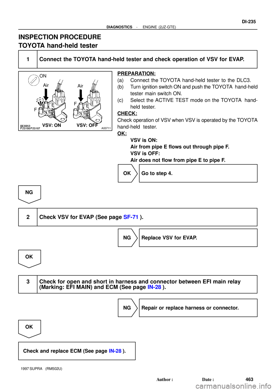
A00711
ON
Air
Air
FEF
E
VSV: ON VSV: OFF
- DIAGNOSTICSENGINE (2JZ-GTE)
DI-235
463 Author�: Date�:
1997 SUPRA (RM502U)
INSPECTION PROCEDURE
TOYOTA hand-held tester
1 Connect the TOYOTA hand-held tester and check operation of VSV for EVAP.
PREPARATION:
(a) Connect the TOYOTA hand-held tester to the DLC3.
(b) Turn ignition switch ON and push the TOYOTA hand-held
tester main switch ON.
(c) Select the ACTIVE TEST mode on the TOYOTA hand-
held tester.
CHECK:
Check operation of VSV when VSV is operated by the TOYOTA
hand-held tester.
OK:
VSV is ON:
Air from pipe E flows out through pipe F.
VSV is OFF:
Air does not flow from pipe E to pipe F.
OK Go to step 4.
NG
2 Check VSV for EVAP (See page SF-71).
NG Replace VSV for EVAP.
OK
3 Check for open and short in harness and connector between EFI main relay
(Marking: EFI MAIN) and ECM (See page IN-28).
NG Repair or replace harness or connector.
OK
Check and replace ECM (See page IN-28).
Page 653 of 1807

FI6973
Throttle Body
Chamber
From
Air
Flow
Meter
To
Cylinder Head
Valve ShaftRotorCoilsValveThrottle
Valve
Air Intake
S03465
Battery
B
W-B
EB
EFI No.1
2A2
R/B
No.2
B-W
22 2
2
5
1
3 2B-Y B-R2
B-R
EA2
EA18
GR24
35
33
34
32A
B
B
B
B
B-R
5
2B1
B2S1
S3
S2
S44
6
1 3
IAC ValveV-Y
G-O
G-W
R-GE01 ISC1
M-REL
B+ ECM
ISC3
ISC2
ISC4
1
EFI Main Relay
R/B
No.2 DI-240
- DIAGNOSTICSENGINE (2JZ-GTE)
468 Author�: Date�:
1997 SUPRA (RM502U)
DTC P0505 Idle Control System Malfunction
CIRCUIT DESCRIPTION
The step motor type IAC valve is located in front of the intake
air chamber. Intake air bypassing the throttle valve is directed
to the IAC valve through a passage. A step motor is built into
the IAC valve. It consists of 4 coils, a magnetic rotor, valve shaft
and valve.
When current flows to the coils due to signals from the ECM, the
rotor turns and moves the valve shaft forward or backward,
changing the clearance between the valve and the valve seat.
In this way the intake air volume bypassing the throttle valve is
regulated, controlling the engine speed.
There are 125 possible positions to which the valve can be
opened.
DTC No.DTC Detecting ConditionTrouble Area
P0505Idle speed continues to vary greatly from the target speed
(2 trip detection logic)
�IAC valve is stuck or closed
�Open or short in IAC valve circuit
�Open or short in A/C signal circuit
�Air intake (hose loose)
WIRING DIAGRAM
DI4T8-01
Page 655 of 1807
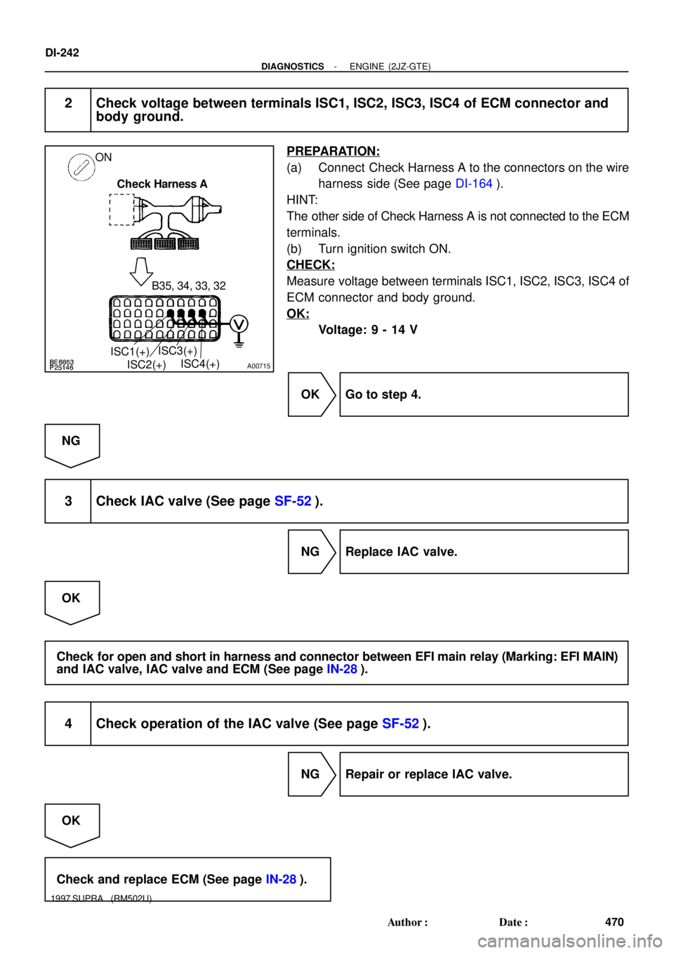
A00715
ON
Check Harness A
B35, 34, 33, 32
ISC1(+)
ISC2(+)ISC3(+)
ISC4(+)
DI-242
- DIAGNOSTICSENGINE (2JZ-GTE)
470 Author�: Date�:
1997 SUPRA (RM502U)
2 Check voltage between terminals ISC1, ISC2, ISC3, ISC4 of ECM connector and
body ground.
PREPARATION:
(a) Connect Check Harness A to the connectors on the wire
harness side (See page DI-164).
HINT:
The other side of Check Harness A is not connected to the ECM
terminals.
(b) Turn ignition switch ON.
CHECK:
Measure voltage between terminals ISC1, ISC2, ISC3, ISC4 of
ECM connector and body ground.
OK:
Voltage: 9 - 14 V
OK Go to step 4.
NG
3 Check IAC valve (See page SF-52).
NG Replace IAC valve.
OK
Check for open and short in harness and connector between EFI main relay (Marking: EFI MAIN)
and IAC valve, IAC valve and ECM (See page IN-28).
4 Check operation of the IAC valve (See page SF-52).
NG Repair or replace IAC valve.
OK
Check and replace ECM (See page IN-28).
Page 663 of 1807

S05428
Battery
B
W-B
EFI No.1
EB
R/B
No.2
2A12
B-D
R/B
No.2
2
2 2 2
51
32
EFI No.2 Relay
B-R L-O
E1 L-O
B-R
B-R 5EA2
BP1
BI
2
W-B
W-B
Fuel
Pump
5 4
L
6BP1
5L-R
FP4 Fuel Pump ECU
B+
B+
E
1DI FPCVSV for
Fuel Pressure
12
W-L
IB1IC2
73
22
21
B
A
A
V-WV-W
V-W
GG
G 1211
124IC2IJ1
IJ1
IC2
DI FPC5VEO1 FPUECM
5
10 DI-248
- DIAGNOSTICSENGINE (2JZ-GTE)
476 Author�: Date�:
1997 SUPRA (RM502U)
DTC P1200 Fuel Pump Relay/ECU Circuit Malfunction
CIRCUIT DESCRIPTION
The fuel pump speed is controlled at 2 steps (high speed, low speed) by the condition of the engine (starting,
light load, heavy load), when the engine starts (STA ON), the ECM sends a Hi signal (about 5 V) to the fuel
pump ECU (FPC terminal).
The fuel pump ECU then outputs Hi voltage (battery positive voltage) to the fuel pump so that the fuel pump
operates at high speed.
After the engine starts, during idling or light loads, the ECM outputs a Low signal (about 2.5 V) to the fuel
pump ECU, the fuel pump ECU outputs Low voltage (about 9 V) to the fuel pump and causes the fuel pump
to operate at low speed.
If the intake air volume increases (high engine load), the ECM sends a Hi signal to the fuel pump ECU and
causes the fuel pump to operate at high speed.
DTC No.DTC Detecting ConditionTrouble Area
Open or short in fuel pump circuit for 1 sec. or more with en-
gine speed 1,000 rpm or less
(2 trip detection logic)
�Open or short in fuelpumpECU circuit
P1200
Open in input circuit of fuel pump ECU (FPC) with engine
speed 1,000 rpm or less
(2 trip detection logic)
�Open or short in fuel pump ECU circuit
�Fuel pump ECU
�ECM power source circuit
�Fuel pump
Open or short in diagnostic signal line (DI) of fuel pump ECU
with engine speed 1,000 rpm or less
(2 trip detection logic)
Fuel um
�ECM
WIRING DIAGRAM
DI4TB-01
Page 664 of 1807

BE6653S03247S03249
A03138
START
5 (+)
8 (-)
- DIAGNOSTICSENGINE (2JZ-GTE)
DI-249
477 Author�: Date�:
1997 SUPRA (RM502U)
INSPECTION PROCEDURE
1 Connect the TOYOTA h")
BE6653S03247S03248
A03137
ON
1(+)
BE6653S03247S03249
A03138
START
5 (+)
8 (-)
- DIAGNOSTICSENGINE (2JZ-GTE)
DI-249
477 Author�: Date�:
1997 SUPRA (RM502U)
INSPECTION PROCEDURE
1 Connect the TOYOTA hand-held tester and check operation of fuel pump
(See page SF-5).
OK Go to step 7.
NG
2 Check voltage of fuel pump ECU power source.
PREPARATION:
(a) Remove LH quarter trim panel (See page SF-83).
(b) Disconnect fuel pump ECU connector.
(c) Turn ignition switch ON.
CHECK:
Measure voltage between terminal 1 of fuel pump ECU connec-
tor and body ground.
OK:
Voltage: 9 - 14 V
NG Check for open and short in harness and con-
nector between EFI main relay (Marking: EFI
MAIN) and fuel pump ECU (See page IN-28).
OK
3 Check voltage between terminals 5 and 8 of fuel pump ECU connector.
PREPARATION:
(a) Remove LH quarter trim panel (See page SF-83).
(b) Disconnect fuel pump ECU connector.
CHECK:
Measure voltage between terminals 5 and 8 of fuel pump ECU
connector when ignition switch is turned to start.
OK:
Voltage: 4.5 - 5.5 V
OK Go to step 5.
NG
Page 685 of 1807
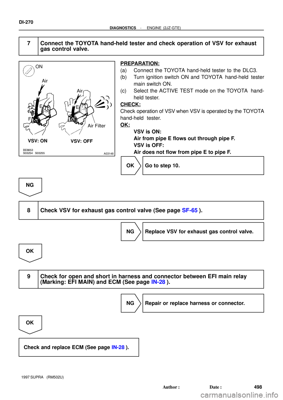
BE6653S03254S03255
A03148
ON
Air
F
VSV: OFF VSV: ONE Air
E
Air Filter
DI-270
- DIAGNOSTICSENGINE (2JZ-GTE)
498 Author�: Date�:
1997 SUPRA (RM502U)
7 Connect the TOYOTA hand-held tester and check operation of VSV for exhaust
gas control valve.
PREPARATION:
(a) Connect the TOYOTA hand-held tester to the DLC3.
(b) Turn ignition switch ON and TOYOTA hand-held tester
main switch ON.
(c) Select the ACTIVE TEST mode on the TOYOTA hand-
held tester.
CHECK:
Check operation of VSV when VSV is operated by the TOYOTA
hand-held tester.
OK:
VSV is ON:
Air from pipe E flows out through pipe F.
VSV is OFF:
Air does not flow from pipe E to pipe F.
OK Go to step 10.
NG
8 Check VSV for exhaust gas control valve (See page SF-65).
NG Replace VSV for exhaust gas control valve.
OK
9 Check for open and short in harness and connector between EFI main relay
(Marking: EFI MAIN) and ECM (See page IN-28).
NG Repair or replace harness or connector.
OK
Check and replace ECM (See page IN-28).
Page 691 of 1807
DI-276
- DIAGNOSTICSENGINE (2JZ-GTE)
504 Author�: Date�:
1997 SUPRA (RM502U)
5 Check for open and short in harness and connector between EFI main relay
(Marking: EFI MAIN) and ECM (See page IN-28).
NG Repair or replace harness or connector.
OK
Check and replace ECM (See page IN-28).
6 Check connection of vacuum hose (See page EC-2).
NG Repair or replace.
OK
7 Check operation of waste gate valve (See page TC-18).
NG Replace No.1 turbocharger.
OK
8 Check operation of exhaust bypass valve (See page TC-18).
NG Replace No.2 turbocharger.
OK
Check and replace ECM (See page IN-28).
Page 703 of 1807
S03469
Battery
EB
B
2A2
1 R/B
No.2
EFI No.1B-W
22 R/B
No.2
35
2 2 2
1 B-R
B-Y5
EA2B-R
8
EA1B-R
EFI Relay
12
G-R38
BVSV3B+ ECM
E01
M-RELVSV2
VSV1E01
B+ E01 39
B
40
B
24
A VSV for Exhaust
Bypass Valve
G-Y
G-B 1
12
2 B-R
B-R
B-R
GR
W-B
VSV for Exhaust
Gas Control Valve
VSV for Intake
Air Control Valve
DI-288
- DIAGNOSTICSENGINE (2JZ-GTE)
516 Author�: Date�:
1997 SUPRA (RM502U)
WIRING DIAGRAM