Page 718 of 1807
S04081BE6653A03406
START
Check Harness A
ECM
B77
STA(+)
- DIAGNOSTICSENGINE (2JZ-GTE)
DI-303
531 Author�: Date�:
1997 SUPRA (RM502U)
OBDII scan tool (excluding TOYOTA hand-held tester)
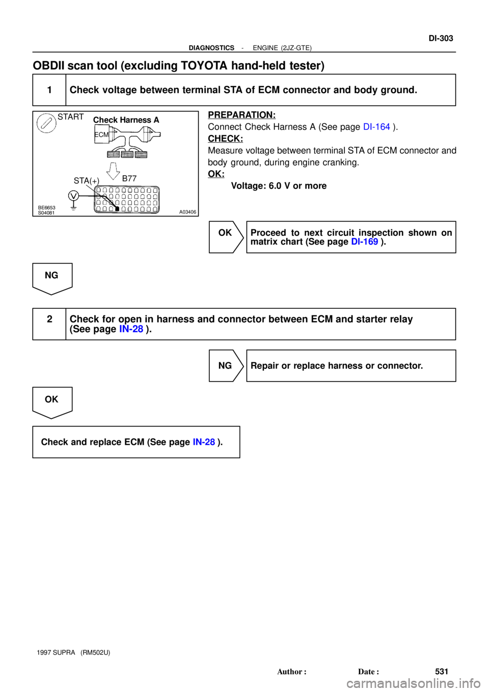
1 Check voltage between terminal STA of ECM connector and body ground.
PREPARATION:
Connect Check Harness A (See page DI-164).
CHECK:
Measure voltage between terminal STA of ECM connector and
body ground, during engine cranking.
OK:
Voltage: 6.0 V or more
OK Proceed to next circuit inspection shown on
matrix chart (See page DI-169).
NG
2 Check for open in harness and connector between ECM and starter relay
(See page IN-28).
NG Repair or replace harness or connector.
OK
Check and replace ECM (See page IN-28).
Page 719 of 1807
S03470
Battery
B
12A
AM2
EFI No.1R/B
No.2 22
W-R
4
IB1W-R7
6
Ignition
Switch
B-W
W-B
B-W
2
2
2 2
EB
EFI Main Relay5
1 3
2 3
1J1E8
IGN
J/B No.1B-O13
II1B-O1
31
24
69A
A
A
B
BR B-Y B-RB-R
GR
EA2
EA1
R/B No.2
ED
E1 M-RELB+ +BE1 IGSWECM
2
8 DI-304
- DIAGNOSTICSENGINE (2JZ-GTE)
532 Author�: Date�:
1997 SUPRA (RM502U)
ECM Power Source Circuit
CIRCUIT DESCRIPTION
When the ignition switch is turned ON, battery positive voltage is applied to the coil, closing the contacts of
the EFI main relay (Marking: EFI) and supplying power to the terminals +B of the ECM.
WIRING DIAGRAM
DI4TU-01
Page 723 of 1807
DI-308
- DIAGNOSTICSENGINE (2JZ-GTE)
536 Author�: Date�:
1997 SUPRA (RM502U)
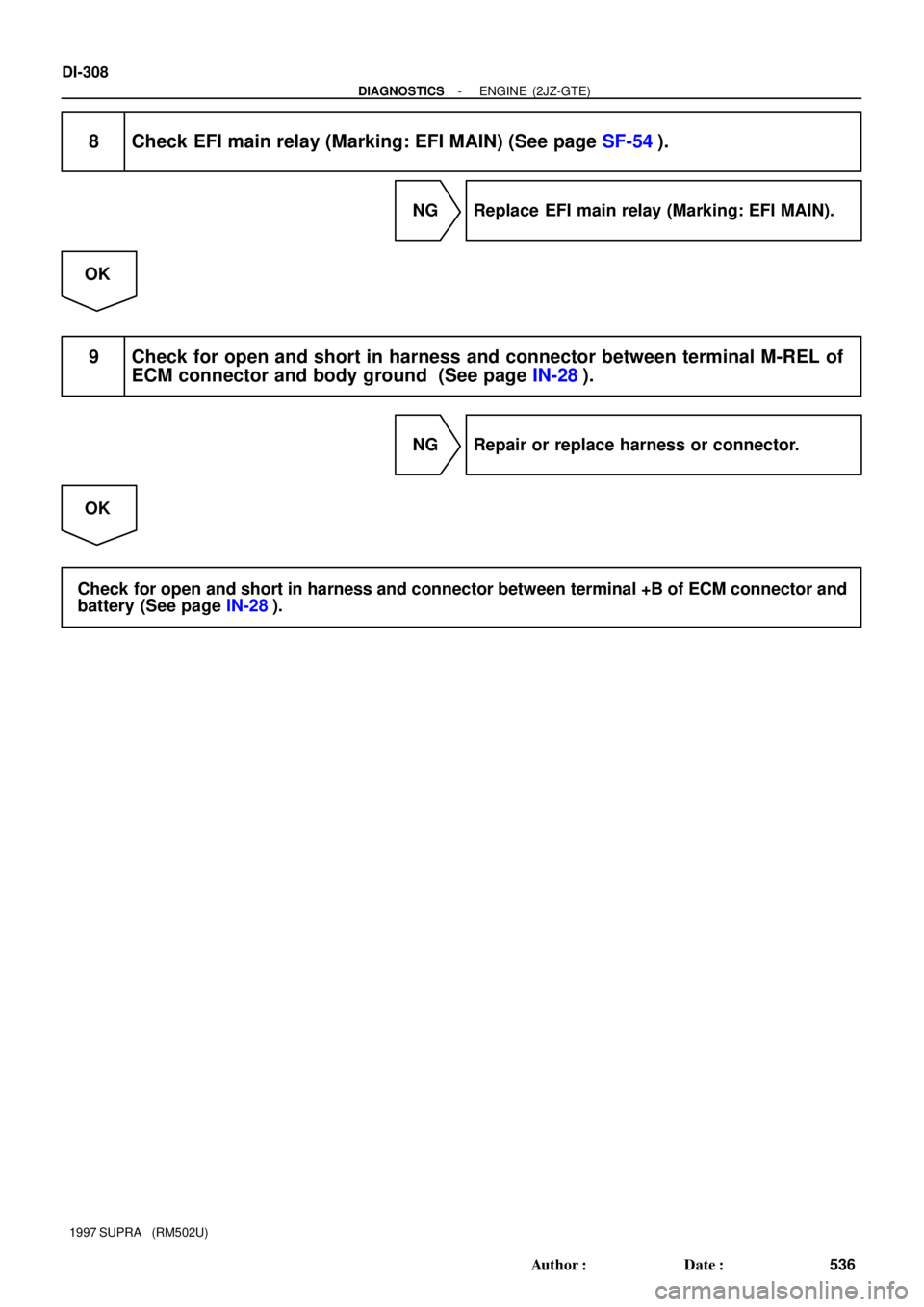
8 Check EFI main relay (Marking: EFI MAIN) (See page SF-54).
NG Replace EFI main relay (Marking: EFI MAIN).
OK
9 Check for open and short in harness and connector between terminal M-REL of
ECM connector and body ground (See page IN-28).
NG Repair or replace harness or connector.
OK
Check for open and short in harness and connector between terminal +B of ECM connector and
battery (See page IN-28).
Page 724 of 1807
FI6897
Pressure
Regulator
From Fuel Tank To
Fuel
Tank
(Return) Intake
Manifold ECMVSV
S03472
Battery
B
EB
W-BEFI No.1
R/B
No.2
1
2A2
B-W
222
2
EFI Relay
R/B
No.2
21 5
3B-R5
EA2
B-Y
EA18
VSV for Fuel
Pressure Control B-R1
2W-L73
B
GR24
AECM
FPU
E01
B+
M-REL
- DIAGNOSTICSENGINE (2JZ-GTE)
DI-309
537 Author�: Date�:
1997 SUPRA (RM502U)
Fuel Pressure Control Circuit
CIRCUIT DESCRIPTION
The ECM turns on a VSV (Vacuum Switching Valve) to draw the
air into the diaphragm chamber of the pressure regulator if it de-
tects that the temperature of the engine coolant is too high dur-
ing engine staring.
The air drawn into the chamber increases the fuel pressure to
prevent fuel vapor lock at high engine temperature in order to
help the engine start when it is warm.
Fuel pressure control ends approx. 120 sec. after the engine is
started.
WIRING DIAGRAM
DI4TV-01
Page 726 of 1807
A00733
ON
Check Harness A
B73
FPU(+)
- DIAGNOSTICSENGINE (2JZ-GTE)
DI-31 1
539 Author�: Date�:
1997 SUPRA (RM502U)
3 Check for open and short in harness and connector between EFI main relay
(Marking: EFI MAIN) and ECM (See page IN-28).
NG Repair or replace harness or connector.
OK
Check and replace ECM (See page IN-28).
OBDII scan tool (excluding TOYOTA hand-held tester)
1 Check VSV for fuel pressure control (See page SF-59).
NG Replace VSV for fuel pressure control.
OK
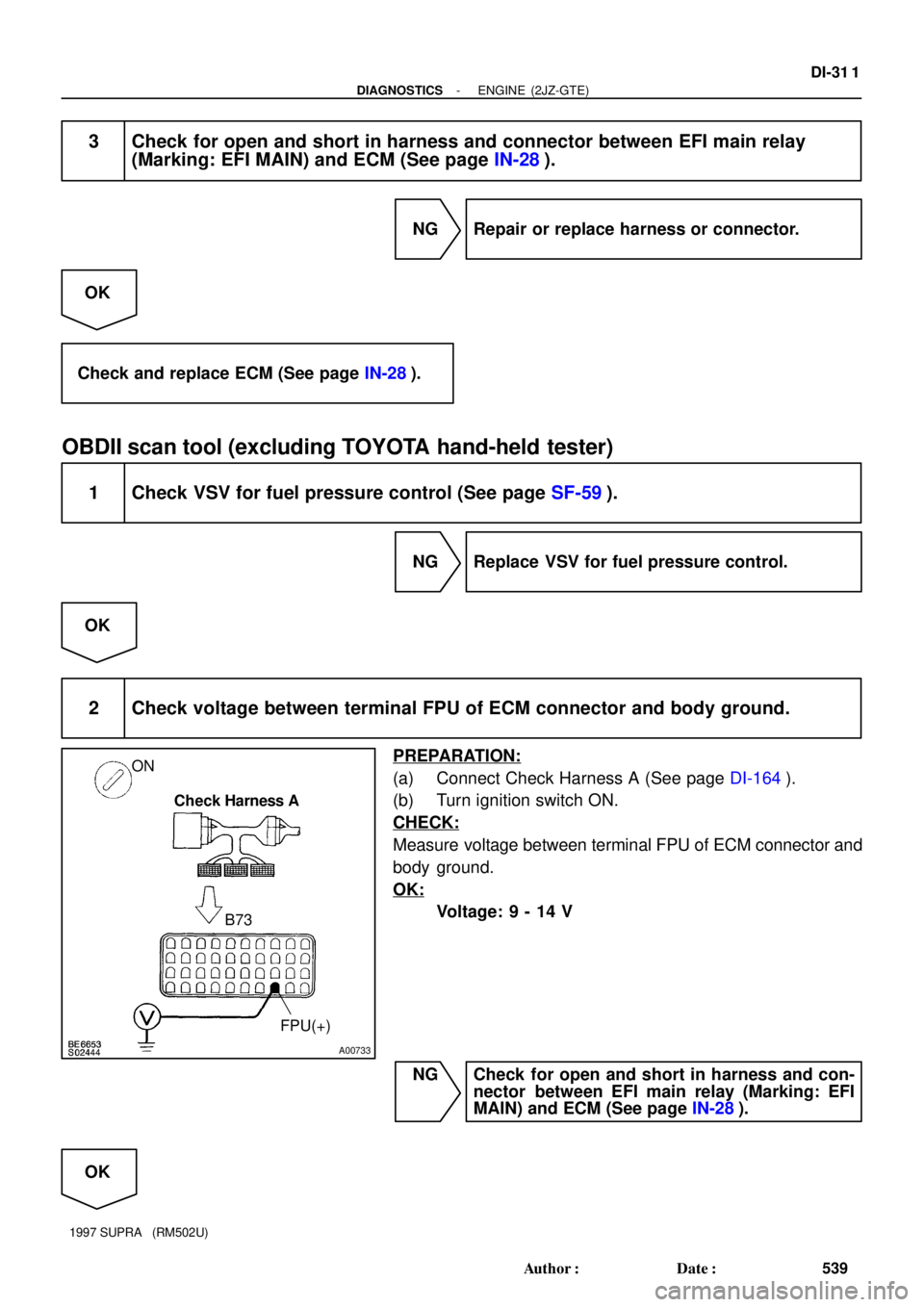
2 Check voltage between terminal FPU of ECM connector and body ground.
PREPARATION:
(a) Connect Check Harness A (See page DI-164).
(b) Turn ignition switch ON.
CHECK:
Measure voltage between terminal FPU of ECM connector and
body ground.
OK:
Voltage: 9 - 14 V
NG Check for open and short in harness and con-
nector between EFI main relay (Marking: EFI
MAIN) and ECM (See page IN-28).
OK
Page 738 of 1807

DIAGNOSTIC TROUBLE CODE CHART
If a malfunction code is displayed during the DTC check, check the circuit l")
DI4V7-01
- DIAGNOSTICSANTI-LOCK BRAKE SYSTEM
DI-447
675 Author�: Date�:
1997 SUPRA (RM502U)
DIAGNOSTIC TROUBLE CODE CHART
If a malfunction code is displayed during the DTC check, check the circuit listed for that code. For details
of each code, turn to the page referred to under the ºSee pageº for the respective ºDTC No.º in the DTC chart.
HINT:
�Using SST 09843-18020, connect the terminals Tc and E1, and remove the short pin.
�If any abnormality is not found when inspect each inspection parts, inspect the ECU.
DTC No.
(See Page)Detection ItemTrouble Area
11
(DI-453)Open circuit in ABS solenoid relay circuit�ABS solenoid relay
�Open or short in ABS solenoid relay circuit
12
(DI-453)Short circuit in ABS solenoid relay circuit�ABS solenoid relay
�B+ short in ABS solenoid relay circuit
13*2
(DI-460)Open circuit in ABS motor relay circuit�ABS motor relay
�Open or short in ABS motor relay circuit
14
(DI-460)Short circuit in ABS motor relay circuit�ABS motor relay
�B+ short in ABS motor relay circuit
21
(DI-466)Open or short circuit in 2-position solenoid circuit for right front
wheel�ABS actuator
�Open or short in SFRH or SFRR circuit
22
(DI-466)Open or short circuit in 2-position solenoid circuit for left front
wheel�ABS actuator
�Open or short in SFLH or SFLR circuit
23
(DI-466)Open or short circuit in 2-position solenoid circuit for right rear
wheel�ABS actuator
�Open or short in SRH (SRRH) or SRR (SRRR) circuit
24*1
(DI-466)
Open or short circuit in 2-position solenoid circuit for left rear
wheel�ABS actuator
�Open or short in SRLH or SRLR circuit
31*2
(DI-469)Right front wheel speed sensor signal malfunction
32*2
(DI-469)Left front wheel speed sensor signal malfunction�Right front, left front, right rear and left rear speed sensor
O htihd iit33*2
(DI-469)Right rear wheel speed sensor signal malfunction
�Open or short in each speed sensor circuit
�Speed sensor rotor
34*2
(DI-469)Left rear wheel speed sensor signal malfunction
41
(DI-475)Low battery positive voltage
�Battery
�IC regulator
�Open or short in power source circuit
43*1
(DI-479)
Malfunction in deceleration sensor
(constant output)�Deceleration sensor
�Wire harness for deceleration sensor system
44*1
(DI-480)Open or short in deceleration sensor circuit�Deceleration sensor
�Open or short in deceleration sensor circuit
45*1
(DI-479)Malfunction in deceleration sensor�Deceleration sensor
�Wire harness for deceleration sensor system
49
(DI-482)Open circuit in stop light switch circuit�Open in stop light circuit
51*2
(DI-484)
Pump motor is locked
Open in pump motor ground�ABS pump motor
Always
ON
(DI-485)Malfunction in ECU
IG power source circuit�Battery
�IC regulator
�Open or short in power source circuit
Page 740 of 1807
DI4V8-01
W02807
2JZ-GE:
2JZ-GTE:
2JZ-GTE:SPORT AVS (2JZ-GTE Engine):
ABS Control
Relay
ABS Solenoid
Relay
ABS Motor RelayABS ActuatorDeceleration Sensor
ABS Warning Light
ABS ECU
DLC1DLC2
Front Speed Sensor RotorRear Speed SensorRear Speed
Sensor Rotor
Front Speed Sensor
- DIAGNOSTICSANTI-LOCK BRAKE SYSTEM
DI-449
677 Author�: Date�:
1997 SUPRA (RM502U)
PARTS LOCATION
Page 744 of 1807

CIRCUIT INSPECTION
DTC 11, 12 ABS Solenoid Relay Circuit
CIRCUIT DESCRIPTION
This relay supplies power to")
DI4VB-01
- DIAGNOSTICSANTI-LOCK BRAKE SYSTEM
DI-453
681 Author�: Date�:
1997 SUPRA (RM502U)
CIRCUIT INSPECTION
DTC 11, 12 ABS Solenoid Relay Circuit
CIRCUIT DESCRIPTION
This relay supplies power to each ABS solenoid. After the ignition switch is turned ON, if the initial check is
OK, the relay goes on.
DTC No.DTC Detecting ConditionTrouble Area
11
Conditions (1) and (2) continue for 0.2 sec. or more:
(1) ABS solenoid relay terminal (SR)
voltage: Below 1.5V
(2) Solenoid relay monitor terminal (AST)
voltage: 0 V
�ABS solenoid relay
�Open or short in ABS solenoid relay circuit
12
Conditions (1) and (2) continue for 0.2 sec. or more:
(1) ABS solenoid relay terminal (SR)
voltage: Battery positive voltage
(2) Solenoid relay monitor terminal (AST)
voltage: Battery positive voltage
�ABS solenoid relay
�B+ short in ABS solenoid relay circuit
Fail safe function:
If trouble occurs in the ABS solenoid relay circuit, the ECU cuts off current to the ABS solenoid relay and
prohibits ABS control.

 Intake
Manifold ECMVSV
S03472
Battery
B
EB
W-BEFI No.1
R/B
No.2
1
2A2
B-W
222
2
EFI Relay
R/B
No.2
21 5
3B-R5
EA2
B-Y
EA18
VSV for Fuel
P")
:
ABS Control
Relay
ABS Solenoid
Relay
ABS Motor RelayABS ActuatorDeceleration Sensor
ABS Warning Light
ABS ECU
DLC1DLC2
Front Speed")