Page 704 of 1807

DI-289
517 Author�: Date�:
1997 SUPRA (RM502U)
INSPECTION PROCEDURE
TOYOTA hand-held tester
1 Con")
BE6653S03252S03253
A03147
ON
Air
Air
Air Filter
E
E
F
VSV: ON
VSV: OFF
- DIAGNOSTICSENGINE (2JZ-GTE)
DI-289
517 Author�: Date�:
1997 SUPRA (RM502U)
INSPECTION PROCEDURE
TOYOTA hand-held tester
1 Connect the TOYOTA hand-held tester and check operation of VSV for IACV.
PREPARATION:
(a) Connect the TOYOTA hand-held tester to DLC3.
(b) Turn ignition switch ON and TOYOTA hand-held tester
main switch ON.
(c) Select the ACTIVE TEST mode on the TOYOTA hand-
held tester.
CHECK:
Check operation of VSV when VSV is operated by the TOYOTA
hand-held tester.
OK:
VSV is ON:
Air from pipe E flows out through pipe F.
VSV is OFF:
Air from pipe E flows out through the air filter.
OK Check for intermittent problems
(See page DI-147).
NG
2 Check VSV for IACV (See page SF-61).
NG Replace VSV for IACV.
OK
3 Check for open and short in harness and connector between EFI main relay
(Marking: EFI MAIN) and ECM (See page IN-28).
NG Repair or replace harness or connector.
OK
Check and replace ECM (See page IN-28).
Page 706 of 1807
S03468
Battery
EB
B
2A2
1 R/B
No.2
EFI No.1B-W
223 5
2 2 2
1
EFI Main Relay W-B
GR
GR 8
EA1 B-R5
EA2B-R12
L-W60
B
VSV for Waste
Gate ValveVSV4B+ ECM
E01
M-RELB+
24
A
- DIAGNOSTICSENGINE (2JZ-GTE)
DI-291
519 Author�: Date�:
1997 SUPRA (RM502U)
DTC P1658 Waste Gate Valve Control Circuit
Malfunction
CIRCUIT DESCRIPTION
Refer to ºBoost Pressure High Malfunctionº on page DI-274.
DTC No.DTC Detecting ConditionTrouble Area
P1658
Under VSV operation condition of the waste gate at repid ac-
celerating, changes of voltage level can be found at the output
terminal (VSV4) of ECM
(2 trip detection logic)�Open or short in VSV circuit for waste gate valve
�VSV for waste gate valve
�ECM
WIRING DIAGRAM
DI4TP-01
Page 707 of 1807
DI-292
- DIAGNOSTICSENGINE (2JZ-GTE)
520 Author�: Date�:
1997 SUPRA (RM502U)
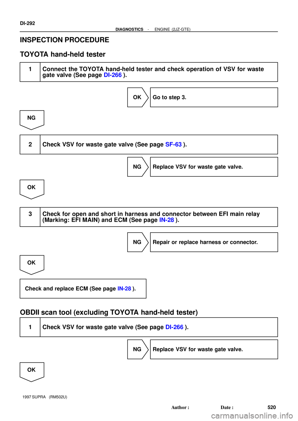
INSPECTION PROCEDURE
TOYOTA hand-held tester
1 Connect the TOYOTA hand-held tester and check operation of VSV for waste
gate valve (See page DI-266).
OK Go to step 3.
NG
2 Check VSV for waste gate valve (See page SF-63).
NG Replace VSV for waste gate valve.
OK
3 Check for open and short in harness and connector between EFI main relay
(Marking: EFI MAIN) and ECM (See page IN-28).
NG Repair or replace harness or connector.
OK
Check and replace ECM (See page IN-28).
OBDII scan tool (excluding TOYOTA hand-held tester)
1 Check VSV for waste gate valve (See page DI-266).
NG Replace VSV for waste gate valve.
OK
Page 711 of 1807
BE6653P24633
A03153
ON
Check Harness A
ECM
B39
VSV2 (+)
DI-296
- DIAGNOSTICSENGINE (2JZ-GTE)
524 Author�: Date�:
1997 SUPRA (RM502U)
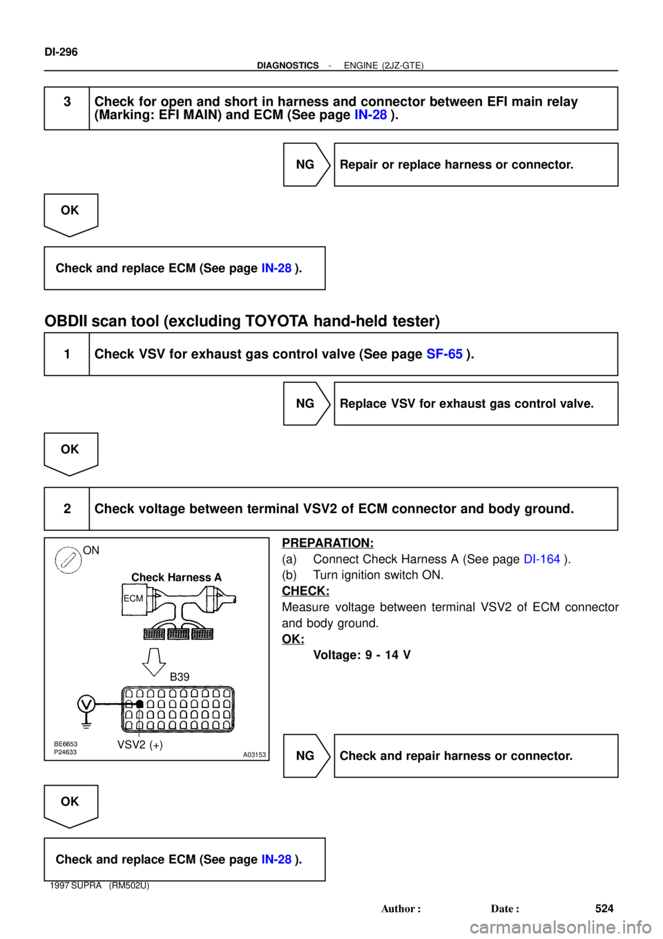
3 Check for open and short in harness and connector between EFI main relay
(Marking: EFI MAIN) and ECM (See page IN-28).
NG Repair or replace harness or connector.
OK
Check and replace ECM (See page IN-28).
OBDII scan tool (excluding TOYOTA hand-held tester)
1 Check VSV for exhaust gas control valve (See page SF-65).
NG Replace VSV for exhaust gas control valve.
OK
2 Check voltage between terminal VSV2 of ECM connector and body ground.
PREPARATION:
(a) Connect Check Harness A (See page DI-164).
(b) Turn ignition switch ON.
CHECK:
Measure voltage between terminal VSV2 of ECM connector
and body ground.
OK:
Voltage: 9 - 14 V
NG Check and repair harness or connector.
OK
Check and replace ECM (See page IN-28).
Page 714 of 1807
BE6653S03239
A03154
ON
Check Harness A
ECM
B38
VSV3 (+)
- DIAGNOSTICSENGINE (2JZ-GTE)
DI-299
527 Author�: Date�:
1997 SUPRA (RM502U)
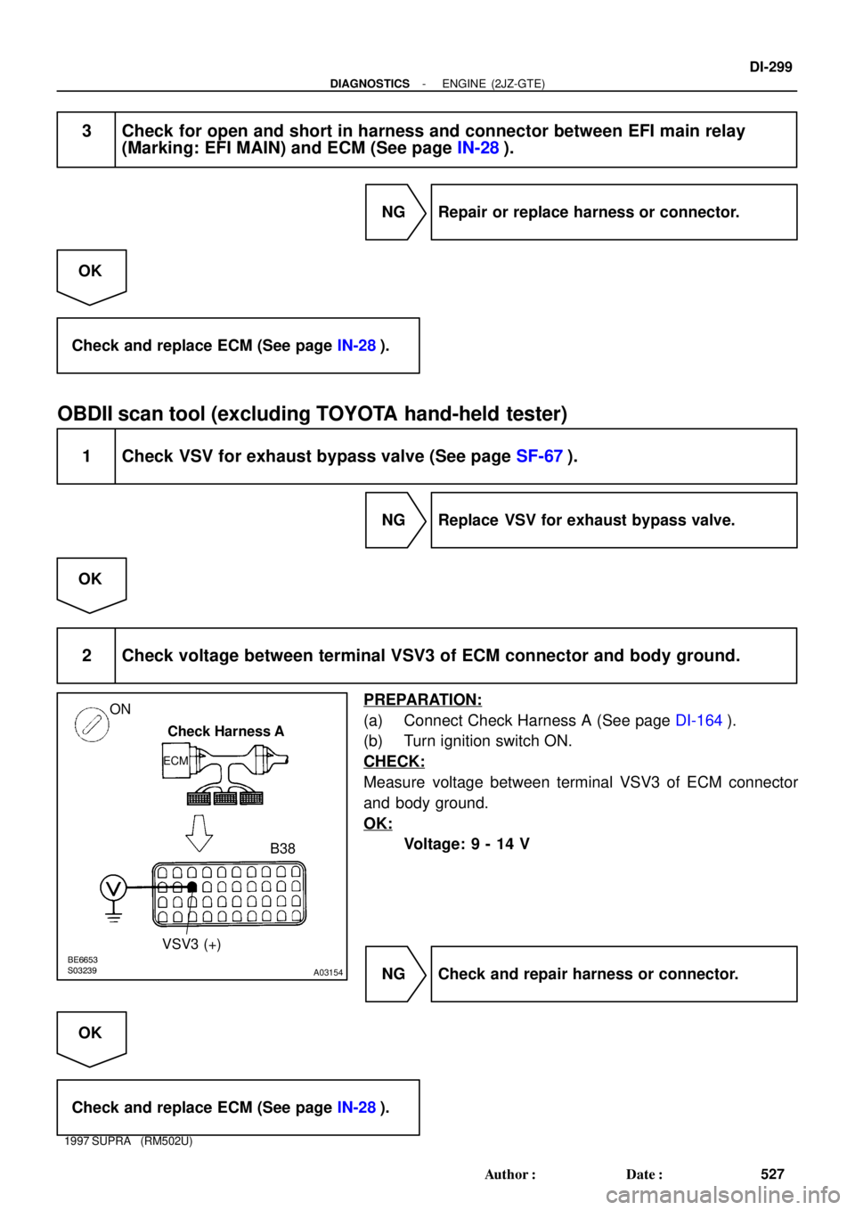
3 Check for open and short in harness and connector between EFI main relay
(Marking: EFI MAIN) and ECM (See page IN-28).
NG Repair or replace harness or connector.
OK
Check and replace ECM (See page IN-28).
OBDII scan tool (excluding TOYOTA hand-held tester)
1 Check VSV for exhaust bypass valve (See page SF-67).
NG Replace VSV for exhaust bypass valve.
OK
2 Check voltage between terminal VSV3 of ECM connector and body ground.
PREPARATION:
(a) Connect Check Harness A (See page DI-164).
(b) Turn ignition switch ON.
CHECK:
Measure voltage between terminal VSV3 of ECM connector
and body ground.
OK:
Voltage: 9 - 14 V
NG Check and repair harness or connector.
OK
Check and replace ECM (See page IN-28).
Page 715 of 1807

528 Author�: Date�:
1997 SUPRA (RM502U)
DTC P1780 Park/Neutral Position Switch Malfunction
CIRCUIT DESCRIPTION
The park/neutral position switch goes on when the")
DI-300
- DIAGNOSTICSENGINE (2JZ-GTE)
528 Author�: Date�:
1997 SUPRA (RM502U)
DTC P1780 Park/Neutral Position Switch Malfunction
CIRCUIT DESCRIPTION
The park/neutral position switch goes on when the shift lever is in the N or P shift position. When it goes on
terminal NSW of the ECM is grounded to body ground via the starter relay thus the terminal NSW voltage
becomes 0 V. When the shift lever is in the D, 2, L or R position, the park/neutral position switch goes off,
so the voltage of ECM terminal NSW becomes battery voltage, the voltage of the ECM internal power source.
If the shift lever is moved from the N position to the D position, this signal is used for air-fuel ratio correction
and for idle speed control (estimated control), etc.
DTC No.DTC Detecting ConditionTrouble Area
2 or more switches are ON simultaneously for ºNº, º2º and ºLº
position
(2 trip detection logic)
Sh t i k/ t l iti it h i it
P1780When driving under conditions (a) and (b) for 30 sec. or more
the park/neutral position switch is ON (N position)
(2 trip detection logic)
(a) Vehicle speed: 70 km/h (44 mph) or more
(b) Engine speed: 1,500 ~ 2,500 rpm�Short in park/neutral position switch circuit
�Park/neutral position switch
�ECM
HINT:
After confirming DTC P1780 use the TOYOTA hand-held tester to confirm the PNP switch signal from ºCUR-
RENT DATAº.
WIRING DIAGRAM
Refer to page DI-373 for the WIRING DIAGRAM
INSPECTION PROCEDURE
Refer to page DI-373 for the INSPECTION PROCEDURE
DI4TS-01
Page 716 of 1807
S05425
Battery 1
B
2A
AM232
MAIN
5
1
Starter Relay
2 2 2 2
W-R
4IB1
W-R
Ignition Switch 78
B-W
J/B No.1 64
ST
1J1KBB13
IJ2B-WB(for MT)
1
2Clutch
Start
Switch
B-W
2
IJ1
BBB B B
B
R/B No.2
L-O810 254
W-B
L-O
L-O
Theft Deterrent
and Door Lock
Control ECU
IH
IB3 IF2
T3T7
Starter 1
S3 B 3
EA1
EA2
1
B
5 6(for AT)
Park/
Neutral
Position
SwitchECM
STA
E1 77
B
- DIAGNOSTICSENGINE (2JZ-GTE)
DI-301
529 Author�: Date�:
1997 SUPRA (RM502U)
Starter Signal Circuit
CIRCUIT DESCRIPTION
When the engine is cranked, the intake air flow is slow, so fuel vaporization is poor. A rich mixture is therefore
necessary in order to achieve good startability. While the engine is being cranked, the battery positive volt-
age is applied to terminal STA of the ECM. The starter signal is mainly used to increase the fuel injection
volume for the starting injection control and after-start injection control.
WIRING DIAGRAM
DI4TT-01
Page 717 of 1807
DI-302
- DIAGNOSTICSENGINE (2JZ-GTE)
530 Author�: Date�:
1997 SUPRA (RM502U)
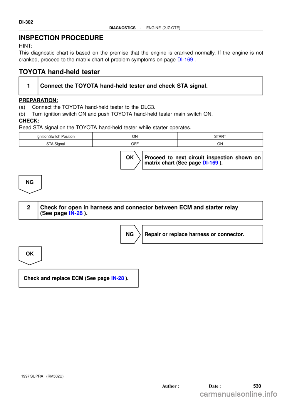
INSPECTION PROCEDURE
HINT:
This diagnostic chart is based on the premise that the engine is cranked normally. If the engine is not
cranked, proceed to the matrix chart of problem symptoms on page DI-169.
TOYOTA hand-held tester
1 Connect the TOYOTA hand-held tester and check STA signal.
PREPARATION:
(a) Connect the TOYOTA hand-held tester to the DLC3.
(b) Turn ignition switch ON and push TOYOTA hand-held tester main switch ON.
CHECK:
Read STA signal on the TOYOTA hand-held tester while starter operates.
Ignition Switch PositionONSTART
STA SignalOFFON
OK Proceed to next circuit inspection shown on
matrix chart (See page DI-169).
NG
2 Check for open in harness and connector between ECM and starter relay
(See page IN-28).
NG Repair or replace harness or connector.
OK
Check and replace ECM (See page IN-28).

DI-")

1
2Clutch
Start
Switch
B-W
2
IJ1
BBB B B
B
R/B No.2
L-O810 254
W-")