Page 170 of 1807

4. INSPEC")
Z07373
Junction Block Side
Connector ºAº
Wire Harness Side
Connector ºBº BE-14
- BODY ELECTRICALIGNITION SWITCH AND KEY UNLOCK WARNING
SWITCH
1992 Author�: Date�:
1997 SUPRA (RM502U)
4. INSPECT RELAY CIRCUIT
Light Auto Turn Off System:
Remove the relay from junction block and inspect the connec-
tors on the wire harness and junction block side, as shown in
the chart.
Tester connectionConditionSpecified condition
A6 - GroundDriver's door courtesy switch OFFNo continuity
A6 - GroundDriver's door courtesy switch ONContinuity
A10 - GroundConstantContinuity
B1 - GroundLight control switch position OFF or TAILNo continuity
B1 - GroundLight control switch position HEADContinuity
B4 - GroundLight control switch position OFFNo continuity
B4 - GroundLight control switch position TAIL or HEADContinuity
A1 - GroundConstantBattery positive voltage
A7 - GroundIgnition switch position LOCK or ACCNo voltage
A7 - GroundIgnition switch position ONBattery positive voltage
B2 - GroundConstantBattery positive voltage
B3 - GroundConstantBattery positive voltage
If the circuit is as specified, try replacing the relay with a new
one.
If the circuit not as specified, inspect the circuits connected to
other parts.
Page 171 of 1807
Z18223
D.R.L. No.3 Relay*
� Combination Switch
Light Control SwitchD.R.L. Main Relay* Headlights
Front Side MarkerR/B No.2
Headlight Control Relay
Headlight Control Relay
(D.R.L.No.2 Relay)
HEAD (LH) Fuse
HEAD (RH) Fuse
HEAD (LH-LWR) Fuse*
HEAD (LH-UPR) Fuse*
HEAD (RH-UPR) Fuse*
Integration Relay
J/B No.1
Taillight Relay
GAUGE Fuse
TAIL Relay
Rear Side MarkerRear Combination Lights
: Daytime Running Light
: CANADA models D.R.L. Headlight Dimmer SwitchHEAD (LH-LWR) Fuse*
Taillights
* � ��
�
�
�
�
�
�
�
�
�
�
BE0DQ-01
- BODY ELECTRICALHEADLIGHT AND TAILLIGHT SYSTEM
BE-15
1993 Author�: Date�:
1997 SUPRA (RM502U)
HEADLIGHT AND TAILLIGHT SYSTEM
LOCATION
Page 173 of 1807

INSPECTION
1.")
Z09366
HEAD
TAIL
Connector ºAºFlash
BE0DS-02
Z09181
34
2 14
3
1
2
Z05930
3
5
21
531 2
- BODY ELECTRICALHEADLIGHT AND TAILLIGHT SYSTEM
BE-17
1995 Author�: Date�:
1997 SUPRA (RM502U)
INSPECTION
1. INSPECT LIGHT CONTROL SWITCH CONTINUITY
Switch positionTester connectionSpecified condition
OFF-No continuity
TAILA2 - A11Continuity
HEADA2 - A11 - A13Continuity
If continuity is not as specified, replace the switch.
2. INSPECT HEADLIGHT DIMMER SWITCH CONTINU-
ITY
Switch positionTester connectionSpecified condition
FlashA9 - A12 - A14Continuity
Low beamA3 - A9Continuity
High beamA9 - A12Continuity
If continuity is not as specified, replace the switch.
3. INSPECT HEADLIGHT CONTROL RELAY CONTINU-
ITY
ConditionTester connectionSpecified condition
Constant3 - 4Continuity
Apply B+ between
terminal 3 and 4.1 - 2Continuity
If continuity is not as specified, replace the relay.
4. INSPECT TAILLIGHT RELAY CONTINUITY
ConditionTester connectionSpecified condition
Constant1 - 2Continuity
Apply B+ between
terminals 1 and 2.3 - 5Continuity
If continuity is not as specified, replace the relay.
5. Light Auto Turn Off System:
INSPECT INTEGRATION RELAY CIRCUIT (See page
BE-13)
Page 174 of 1807

6. INSPECT DOOR COURTESY SWITCH CONTINUITY
(See page BE-28")
Z07503
Wire Harness Side
Z09181
34
2 143
12 BE-18
- BODY ELECTRICALHEADLIGHT AND TAILLIGHT SYSTEM
1996 Author�: Date�:
1997 SUPRA (RM502U)
6. INSPECT DOOR COURTESY SWITCH CONTINUITY
(See page BE-28)
7. CANADA models only:
INSPECT D.R.L. MAIN RELAY CIRCUIT
Disconnect the connector from relay and inspect the connector
on wire harness side, as shown.
Tester connectionConditionSpecified condition
5 - GroundHeadlight dimmer switch position Low beam or
high beamNo continuity
5 - GroundHeadlight dimmer switch position FlashContinuity
8 - GroundParking brake switch position OFFNo continuity
8 - GroundParking brake switch position ONContinuity
16 - GroundHeadlight dimmer switch position Low beamNo continuity
16 - GroundHeadlight dimmer switch position Flash or High
beamContinuity
13 - GroundConstantContinuity
18 - GroundConstantContinuity
2 - GroundIgnition switch position LOCK or ACCNo voltage
2 - GroundIgnition switch position ONBattery positive voltage
11 - GroundEngine StopNo voltage
11 - GroundEngine RunningBattery positive voltage
15 - Ground
17 - GroundConstantBattery positive voltage
If the circuit is as specified, try replacing the relay with a new
one.
If the circuit is not as specified, inspect the circuit connected to
other parts.
8. INSPECT D.R.L. NO.2 RELAY CONTINUITY
ConditionTester connectionSpecified condition
Constant3 - 4Continuity
Apply B+ between
terminals 3 and 4.1 - 2Continuity
If continuity is not as specified, replace the relay.
Page 175 of 1807
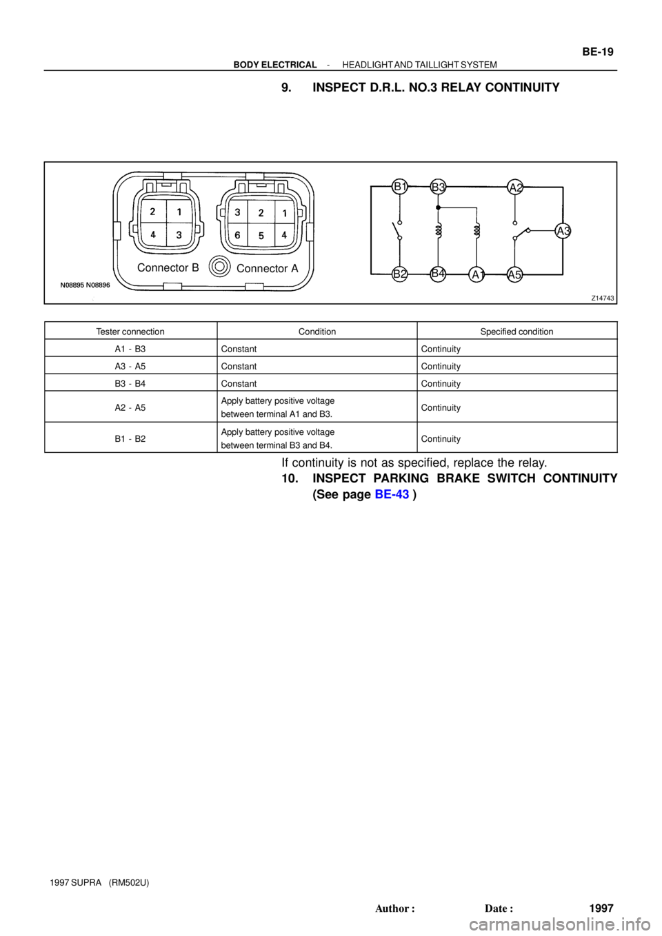
Z14743
Connector B
Connector AB1
B3
B2B4
A1 A5A3 A2
- BODY ELECTRICALHEADLIGHT AND TAILLIGHT SYSTEM
BE-19
1997 Author�: Date�:
1997 SUPRA (RM502U)
9. INSPECT D.R.L. NO.3 RELAY CONTINUITY
Tester connectionConditionSpecified condition
A1 - B3ConstantContinuity
A3 - A5ConstantContinuity
B3 - B4ConstantContinuity
A2 - A5Apply battery positive voltage
between terminal A1 and B3.Continuity
B1 - B2Apply battery positive voltage
between terminal B3 and B4.Continuity
If continuity is not as specified, replace the relay.
10. INSPECT PARKING BRAKE SWITCH CONTINUITY
(See page BE-43)
Page 178 of 1807
BE0DU-03
Z18225
Headlights
� Fog Lights
R/B No.2
� Fog Light Relay
� FOG Fuse
� HEAD Fuse
Fog Light Switch BE-22
- BODY ELECTRICALFOG LIGHT SYSTEM
2000 Author�: Date�:
1997 SUPRA (RM502U)
FOG LIGHT SYSTEM
LOCATION
Page 179 of 1807
N19593
ON
Connector ºAº
BE0DV-03
Z07377
- BODY ELECTRICALFOG LIGHT SYSTEM
BE-23
2001 Author�: Date�:
1997 SUPRA (RM502U)
INSPECTION
1. INSPECT FOG LIGHT SWITCH CONTINUITY
Switch positionTester connectionSpecified condition
OFF-No continuity
ONA6 - A7Continuity
If continuity is not as specified, replace the switch.
2. INSPECT FOG LIGHT RELAY CONTINUITY
ConditionTester connectionSpecified condition
Constant1 - 2Continuity
Apply B+ between
terminals 1 and 2.3 - 5Continuity
If continuity is not as specified, replace the relay.
Page 183 of 1807
Z18226
Personal LightDoor Key Lock and Unlock Switch
Door Lock Motor and Unlock Detection Switch
Luggage Room Light Switch
Luggage Room Light
Door Courtesy Switches Door Lock Motor and
Unlock Detection Switch �R/B No.2Integration
Relay
DOME Fuse
BE0DZ-01
- BODY ELECTRICALINTERIOR LIGHT SYSTEM
BE-27
2005 Author�: Date�:
1997 SUPRA (RM502U)
INTERIOR LIGHT SYSTEM
LOCATION