Page 1604 of 1807
SR149-01
R11266
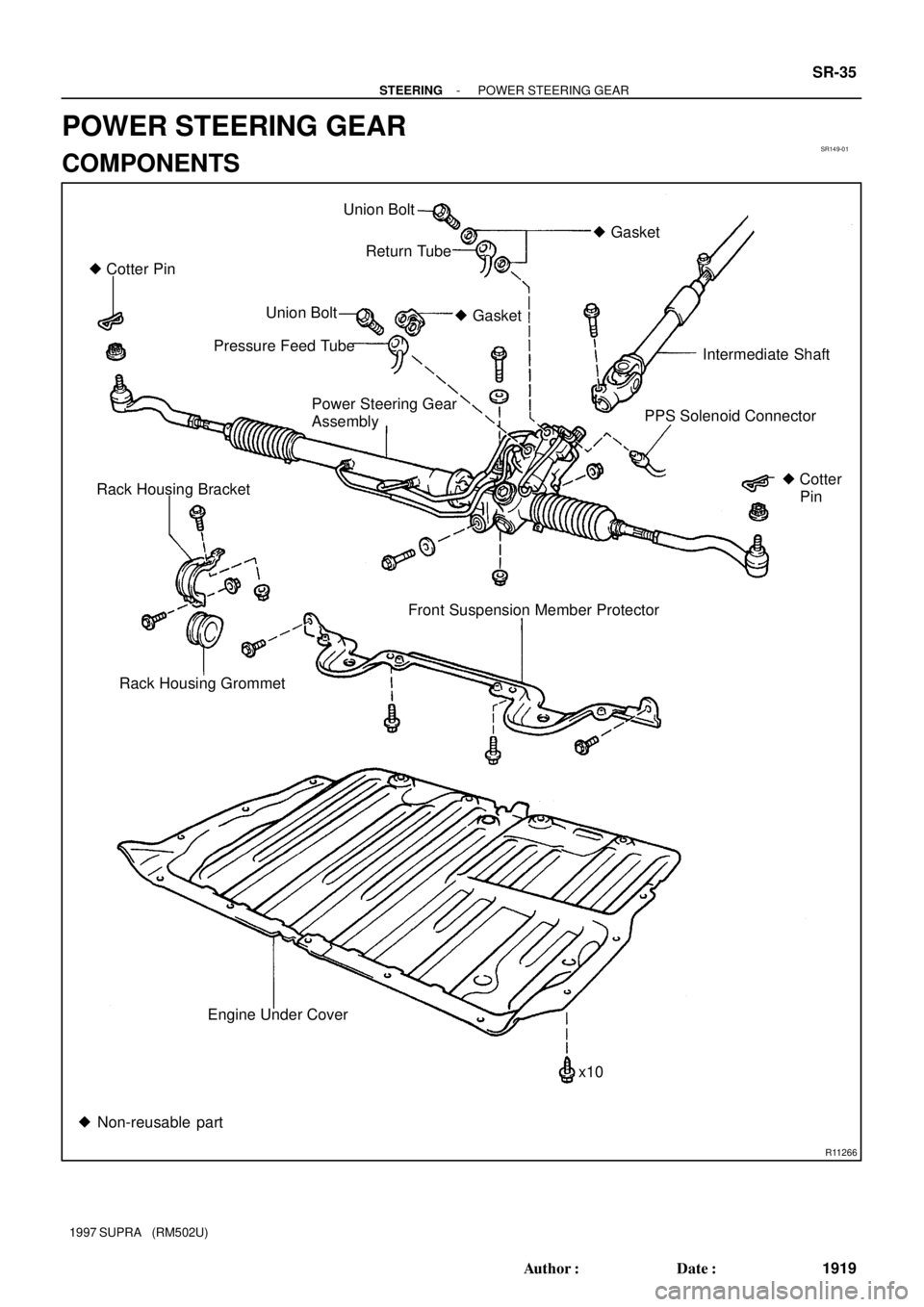
� Cotter PinUnion Bolt
� Gasket
Return Tube
Union Bolt
Intermediate Shaft � Gasket
Pressure Feed Tube
Power Steering Gear
AssemblyPPS Solenoid Connector
Rack Housing Bracket
Rack Housing Grommet
� Cotter
Pin
Front Suspension Member Protector
Engine Under Cover
x10
� Non-reusable part
- STEERINGPOWER STEERING GEAR
SR-35
1919 Author�: Date�:
1997 SUPRA (RM502U)
POWER STEERING GEAR
COMPONENTS
Page 1605 of 1807
SR-36
- STEERINGPOWER STEERING GEAR
1920 Author�: Date�:
1997 SUPRA (RM502U)
Page 1606 of 1807
Z18140
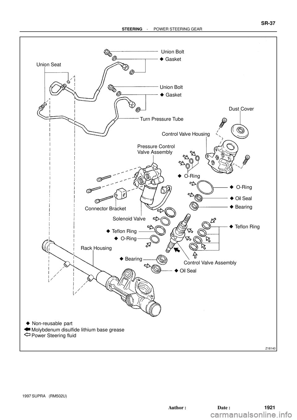
Union SeatUnion Bolt
� Gasket
Union Bolt
� Gasket
Turn Pressure TubeDust Cover
Control Valve Housing
Pressure Control
Valve Assembly
� O-Ring
� Oil Seal � O-Ring
� Bearing
� Teflon Ring Connector Bracket
Solenoid Valve
Control Valve Assembly � Teflon Ring
� O-Ring
� Oil Seal � Bearing Rack Housing
� Non-reusable part
Molybdenum disulfide lithium base grease
Power Steering fluid
- STEERINGPOWER STEERING GEAR
SR-37
1921 Author�: Date�:
1997 SUPRA (RM502U)
Page 1607 of 1807
SR14A-01
SR-38
- STEERINGPOWER STEERING GEAR
1922 Author�: Date�:
1997 SUPRA (RM502U)
REMOVAL
1. PLACE FRONT WHEELS FACING STRAIGHT AHEAD
2. REMOVE STEERING WHEEL PAD
(See page SR-1 1)
3. REMOVE STEERING WHEEL
(See page SR-1 1)
4. REMOVE ENGINE UNDER COVER
Remove the 10 bolts.
5. REMOVE FR SUSPENSION MEMBER PROTECTOR
Remove the 4 bolts.
6. DISCONNECT INTERMEDIATE SHAFT
(See page SR-1 1)
7. DISCONNECT RH AND LH TIE ROD ENDS
(See page SA-12)
8. DISCONNECT PRESSURE FEED TUBE
Remove the union bolt and gasket.
9. DISCONNECT RETURN TUBE
Remove the union bolt and 2 gaskets.
10. DISCONNECT PPS SOLENOID CONNECTOR
11. REMOVE RACK HOUSING BRACKET AND GROMMET
Remove the 2 bolts and nuts.
12. REMOVE PS GEAR ASSEMBLY
Remove the 2 bolts and nuts.
Page 1608 of 1807

DISASSEMBLY
NOTICE:
When using a vise, do not ove")
SR14B-01
R06961
SST
R07510
SST
SR4371Matchmarks
Z06090
Chisel
R07107SST
- STEERINGPOWER STEERING GEAR
SR-39
1923 Author�: Date�:
1997 SUPRA (RM502U)
DISASSEMBLY
NOTICE:
When using a vise, do not overtighten it.
1. SECURE PS GEAR ASSEMBLY IN VISE
Using SST, secure the gear assembly in a vise.
SST 09612-00012
2. REMOVE 2 TURN PRESSURE TUBES
(a) Remove the union bolt and 2 gaskets.
(b) Using SST, remove the tube.
SST 09633-00020
(c) Remove the 2 union seats from the rack housing.
3. REMOVE RH AND LH TIE ROD ENDS AND LOCK
NUTS
Place matchmarks on the tie rod end and rack end, and loosen
the lock nut.
4. REMOVE RH AND LH CLIPS, RACK BOOTS AND
CLAMPS
NOTICE:
�Be careful not to damage the boot.
�Mark the RH and LH boots.
5. REMOVE RH AND LH RACK ENDS AND CLAW WASH-
ERS
(a) Using a chisel and a hammer, unstake the washer.
NOTICE:
Avoid any impact to the steering rack.
(b) Using a spanner (22 mm) to hold the steering rack and us-
ing SST, remove the rack end.
SST 09922-10010
NOTICE:
�Use SST 09922-10010 in the direction shown in the il-
lustration.
�Mark the RH and LH rack ends.
Page 1609 of 1807

6. REMOVE RACK GUIDE SPRING CAP LOCK NUT
Using")
R07108
SST
R07439
SST
Self-Locking
Nut
R07336
Vinyl Tape
R07099
Vinyl Tape SR-40
- STEERINGPOWER STEERING GEAR
1924 Author�: Date�:
1997 SUPRA (RM502U)
6. REMOVE RACK GUIDE SPRING CAP LOCK NUT
Using SST, remove the nut.
SST 09922-10010
NOTICE:
Use SST 09922-10010 in the direction shown in the illustra-
tion.
7. REMOVE RACK GUIDE SPRING CAP, RACK GUIDE
SPRING, RACK GUIDE AND RACK GUIDE SEAT
Using a hexagon wrench (24 mm), remove the cap.
8. REMOVE RACK HOUSING CAP
9. REMOVE SELF- LOCKING NUT, BEARING AND
SPACER
Using SST to stop the control valve shaft rotating, remove the
nut.
SST 09616-00010
10. REMOVE DUST COVER
11. REMOVE CONTROL VALVE HOUSING WITH CON-
TROL VALVE ASSEMBLY
(a) To prevent oil seal lip damage, wind vinyl tape on the ser-
rated part of the control valve shaft.
(b) Using a hexagon wrench (6 mm), remove the 2 bolts.
(c) Remove the O-ring from the housing.
12. REMOVE CONTROL VALVE ASSEMBLY
Using a plastic hammer, tap out the control valve.
NOTICE:
Be careful not to damage the oil seal lip.
13. REMOVE CYLINDER END STOPPER AND 2 SPACERS
Using snap ring pliers, remove the snap ring from the rack hous-
ing.
Page 1610 of 1807
R07362
Press
Socket Wrench
Extension Bar
W00208
Press
SST
Spacer
SST
Oil Seal
- STEERINGPOWER STEERING GEAR
SR-41
1925 Author�: Date�:
1997 SUPRA (RM502U)
14. REMOVE STEERING RACK AND OIL SEAL
(a) Using an extension bar or brass bar and a press, press
out the rack with the oil seal.
NOTICE:
Take care not to drop the rack.
(b) Remove the oil seal from the rack.
15. REMOVE OIL SEAL AND SPACER
Using SST, press out the oil seal and spacer.
SST 09950-60010 (09951-00280),
09950-70010 (09951-07200)
Page 1611 of 1807

INSP")
SR14C-01
R10072
R07288
A
B
C
BearingSST
R07109
Cutouts
SST
Oil Seal
W00209
Press
SST
Oil Seal
SST
W00210
SST
Bearing SR-42
- STEERINGPOWER STEERING GEAR
1926 Author�: Date�:
1997 SUPRA (RM502U)
INSPECTION
NOTICE:
When using a vise, do not overtighten it.
1. INSPECT STEERING RACK
(a) Using a dial indicator, check the rack for runout and for
teeth wear or damage.
Maximum runout: 0.30mm (0.018 in.)
(b) Check the back surface for wear or damage.
2. IF NECESSARY, REPLACE OIL SEAL AND BEARING
(a) Set SST to the rack housing, as shown.
SST 09612-30012
(b) Turn A clockwise and engage the tips of C on the bearing.
(c) Using a spanner (8 mm), keep A fixed while turning nut B
clockwise, and remove the bearing.
NOTICE:
Be careful not to damage the rack housing.
(d) Using SST, remove the oil seal from the rack housing.
SST 09612-30012
NOTICE:
Be careful not to damage the rack housing.
HINT:
When using SST, apply the tips of SST to the cutouts in the rack
housing.
(e) Coat a new oil seal lip with power steering fluid.
(f) Using SST, press in the oil seal.
SST 09950-60010 (09951-00280, 09951-00390,
09952-06010), 09950-70010 (09951-07100)
NOTICE:
Make sure to install the oil seal facing the correct direction.
(g) Using SST, press in the bearing.
SST 09950-60010 (09951-00460),
09950-70010 (09951-07100)