Page 384 of 1807
ABS Antilock Brake System
A/C Air Conditioner
assy assembly
ECT Electronic Controlled Transmission
ECU Electronic Control Unit
e.g. Exempli Gratia (for Example)
Ex. Except
FWD Front Wheel Drive Vehicles
4WD Four Wheel Drive Vehicles
in. inch
LH Left-hand
LHD Left-hand Drive
MIG Metal Inert Gas
M/Y Model Year
PPS Progressive Power Steering
RH Right-hand
RHD Right-hand Drive
SRS Supplemental Restraint System
w/ with
w/o without
ABBREVIATIONS USED IN THIS MANUAL
For convenience, the following abbreviations are used in this
manual.
INTRODUCTIONIN-16
Page 652 of 1807

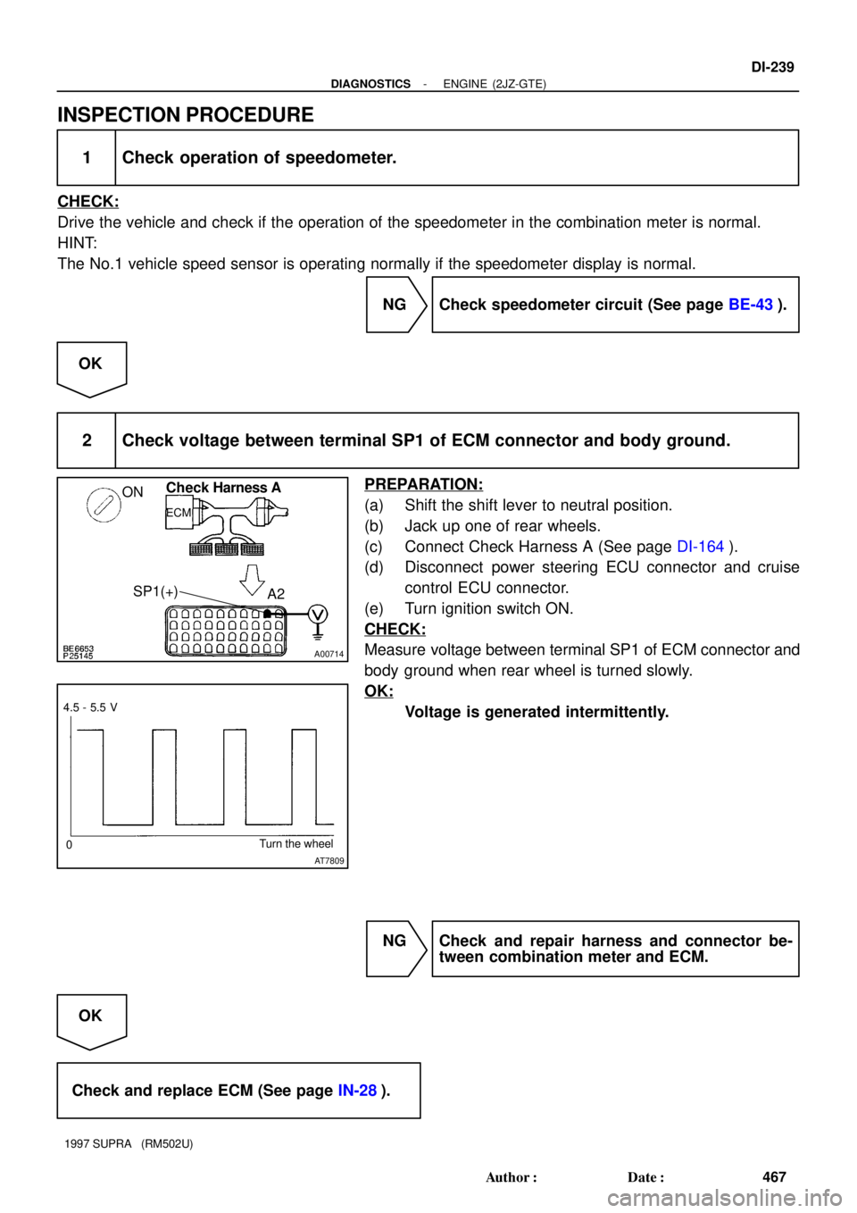
A00714
ONCheck Harness A
ECM
A2 SP1(+)
AT7809
4.5 - 5.5 V
0Turn the wheel
- DIAGNOSTICSENGINE (2JZ-GTE)
DI-239
467 Author�: Date�:
1997 SUPRA (RM502U)
INSPECTION PROCEDURE
1 Check operation of speedometer.
CHECK:
Drive the vehicle and check if the operation of the speedometer in the combination meter is normal.
HINT:
The No.1 vehicle speed sensor is operating normally if the speedometer display is normal.
NG Check speedometer circuit (See page BE-43).
OK
2 Check voltage between terminal SP1 of ECM connector and body ground.
PREPARATION:
(a) Shift the shift lever to neutral position.
(b) Jack up one of rear wheels.
(c) Connect Check Harness A (See page DI-164).
(d) Disconnect power steering ECU connector and cruise
control ECU connector.
(e) Turn ignition switch ON.
CHECK:
Measure voltage between terminal SP1 of ECM connector and
body ground when rear wheel is turned slowly.
OK:
Voltage is generated intermittently.
NG Check and repair harness and connector be-
tween combination meter and ECM.
OK
Check and replace ECM (See page IN-28).
Page 851 of 1807

DI4WG-01
DI-560
- DIAGNOSTICSSUPPLEMENTAL RESTRAINT SYSTEM
788 Author�: Date�:
1997 SUPRA (RM502U)
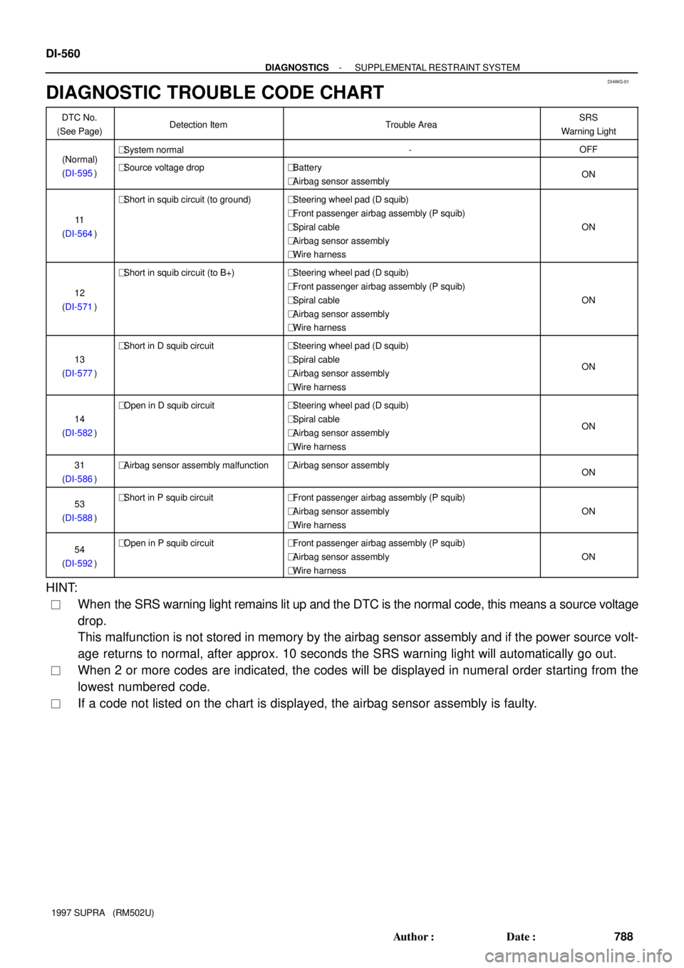
DIAGNOSTIC TROUBLE CODE CHART
DTC No.
(See Page)Detection ItemTrouble AreaSRS
Warning Light
(N l)�System normal-OFF(Normal)
(DI-595)�Source voltage drop�Battery
�Airbag sensor assemblyON
11
(DI-564)
�Short in squib circuit (to ground)�Steering wheel pad (D squib)
�Front passenger airbag assembly (P squib)
�Spiral cable
�Airbag sensor assembly
�Wire harness
ON
12
(DI-571)
�Short in squib circuit (to B+)�Steering wheel pad (D squib)
�Front passenger airbag assembly (P squib)
�Spiral cable
�Airbag sensor assembly
�Wire harness
ON
13
(DI-577)
�Short in D squib circuit�Steering wheel pad (D squib)
�Spiral cable
�Airbag sensor assembly
�Wire harness
ON
14
(DI-582)
�Open in D squib circuit�Steering wheel pad (D squib)
�Spiral cable
�Airbag sensor assembly
�Wire harness
ON
31
(DI-586)�Airbag sensor assembly malfunction�Airbag sensor assemblyON
53
(DI-588)�Short in P squib circuit�Front passenger airbag assembly (P squib)
�Airbag sensor assembly
�Wire harness
ON
54
(DI-592)�Open in P squib circuit�Front passenger airbag assembly (P squib)
�Airbag sensor assembly
�Wire harness
ON
HINT:
�When the SRS warning light remains lit up and the DTC is the normal code, this means a source voltage
drop.
This malfunction is not stored in memory by the airbag sensor assembly and if the power source volt-
age returns to normal, after approx. 10 seconds the SRS warning light will automatically go out.
�When 2 or more codes are indicated, the codes will be displayed in numeral order starting from the
lowest numbered code.
�If a code not listed on the chart is displayed, the airbag sensor assembly is faulty.
Page 1015 of 1807
16
ABBREVIATIONS D
ABBREVIATIONS
The follow abbreviations are used in this manual.
ABS = Anti-Lock Brake Systerm O/D = Overdrive
A/C = Air Conditioning PPS = Progressive Power Steering
ACIS = Acoustic Control Induction System R/B = Relay Block
A/T = Automatic Transmission RH = Right-Hand
COMB. = Combination SFI = Sequential Multiport Fuel Injection
ECU. = Electronic Control Unit SRS = Supplemental Restraint System
EGR = Exhaust Gas Recirculation SW = Switch
ESA = Electronic Spark Advance TEMP. = Temperature
EVAP = Evaporative Emission TRAC = Traction Control
J/B = Junction Block VSV = Vacuum Switching Valve
LH = Left-Hand w/ = With
M/T = Manual Transmission w/o = Without
* The titles given inside the components are the names of the terminals (terminal codes) and are not treated
as being abbreviations.
Page 1027 of 1807
![TOYOTA SUPRA 1997 Service Repair Manual 27
G
Position of Parts in Engine Compartment
[2JZ-GE]
O 2 Oil Pressure SW
P 1 PPS Solenoid
P 2 Park/Neutral Position SW, Back-Up Light SW and
A/T Indicator Light SW (A/T)
P 3 Power Steering Pressure S TOYOTA SUPRA 1997 Service Repair Manual 27
G
Position of Parts in Engine Compartment
[2JZ-GE]
O 2 Oil Pressure SW
P 1 PPS Solenoid
P 2 Park/Neutral Position SW, Back-Up Light SW and
A/T Indicator Light SW (A/T)
P 3 Power Steering Pressure S](/manual-img/14/57469/w960_57469-1026.png)
27
G
Position of Parts in Engine Compartment
[2JZ-GE]
O 2 Oil Pressure SW
P 1 PPS Solenoid
P 2 Park/Neutral Position SW, Back-Up Light SW and
A/T Indicator Light SW (A/T)
P 3 Power Steering Pressure SW
P13 Parking Light LH
S 2 Starter
S 3 Starter
T 1 Theft Deterrent Horn
T 2 Throttle Position Sensor
V 1 VSV (ACIS)
V 2 VSV (EGR)
V 3 VSV (EVAP)
V 6 VSV (Fuel Pressure Up)
V10 Vehicle Speed Sensor No.1 (Combination Meter)
V11 Vehicle Speed Sensor No.2 (Electronically
Controlled Transmission)
W 1 Washer Motor H 1 Headlight Hi LH
H 2 Headlight Hi RH
H 3 Headlight Lo LH
H 4 Headlight Lo RH
H 8 Horn LH
H 9 Horn RH
I 1 Idle Air Control Valve
I 4 Igniter
I 5 Ignition Coil
I 12 Injector No.1
I 13 Injector No.2
I 14 Injector No.3
I 15 Injector No.4
I 16 Injector No.5
I 17 Injector No.6
K 1 Knock Sensor (on Front Side)
K 2 Knock Sensor (on Rear Side)
M 1 Mass Air Flow Meter
M 2 Main Heated Oxygen Sensor (Bank 1 Sensor 1)
M 3 Main Heated Oxygen Sensor (Bank 2 Sensor 1)
N 1 Noise Filter
Page 1045 of 1807

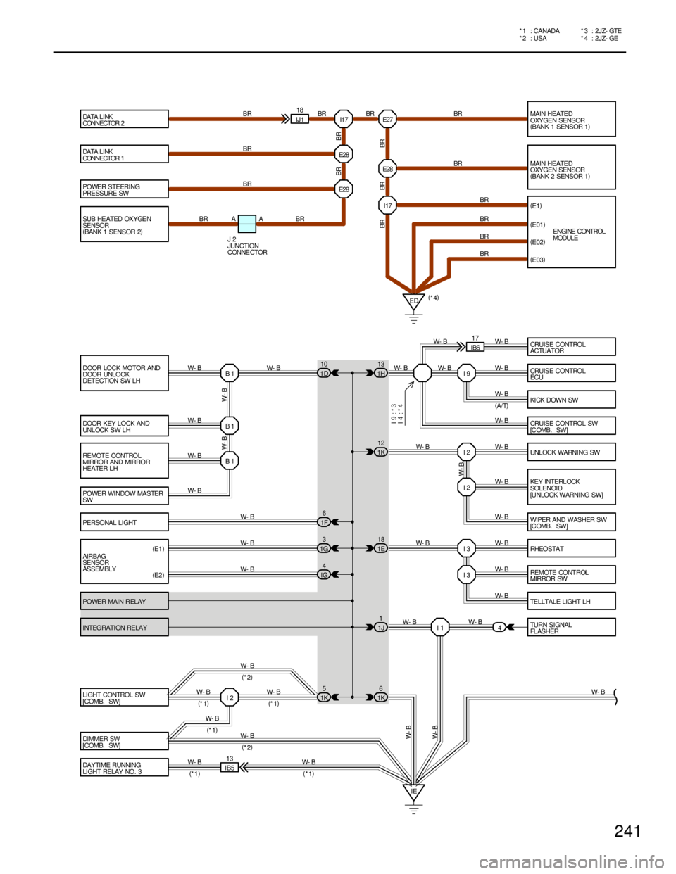
POWER STEERING
PRESSURE SW
DOOR LOCK MOTOR AND
DOOR UNLOCK
DETECTION SW LH
DOOR KEY LOCK AND
UNLOCK SW LH
REMOTE CONTROL
MIRROR AND MIRROR
HEATER LH
POWER WINDOW MASTER
SW
PERSONAL LI GHT
AIRBAG
SENSOR
ASSEMBLY
POWER MAIN RELAY
INTEGRATION RELAY
LIGHT CONTROL SW
[COMB. SW]
DI MME R SW
[COMB. SW]
DAYTIME RUNNING
LI GHT RELAY NO . 3MAIN HEATED
OXYGEN SENSOR
(
BANK 1 SENSOR 1)
MAIN HEATED
OXYGEN SENSOR
(
BANK 2 SENSOR 1)
(
E1)
CRUISE CONTROL
ECU
KI CK DOWN SW
CRUISE CONTROL SW
[C OMB . SW ]
UNLOCK WA RNI NG SW
KEY INTERL OCK
SOLENOI D
[UNLOCK WARNING SW]
WIPER AND WASHER SW
[C OMB . SW ]
RHEOSTAT
RE MOTE CO NT ROL
MIRROR SW
TELLTALE LIGHT LH
TURN SIGNAL
FL AS HER I17 E27
E28
I17
I 9
I 2
I 2
I 3
I 3
I 1 B 1 B 1 B 1IJ118
ED E28
4
IE(
E01)
(
E02)
W- B
W- B
IB513
W- B
(
*1) W- B
(
*1)(
*4) BR BR BR
BR
BR
BR
BR BR
BR
BR
W- B
W- B
W- B
W- B
W- B
W- B
W- B
W- B W- BW- B W- B W- B
W- B W- B W- B W- B W- B W- B W- B
W- B
W- B
W- BBR
BR BR BR W- B W- B
(
E1)
(
E2)W- B
W- B
W- B
W- B W- B DA TA L I NK
CONNECTOR 2
DA TA L I NK
CONNECTOR 1
E NGI NE CONTROL
MODULE
(
A/T) BR
(
E03)
I 2W- B
W- B
W- B(
*2)
(
*1)
(
*1)(
*1)
(
*2) SUB HE ATED OXYGE N
SENSOR
(
BANK 1 SENSOR 2)E28
BR A A BR
J 2
JUNCTION
CONNE CTOR
BR
CRUISE CONTROL
ACTUATOR W- B
IB617
W- B
I 9 : * 3
I 4 : * 4
1H13
1K12
1E18
1J1
1K6 1D10
1F6
1G3
IG4
1K5
241
* 4 : 2JZ- GE *2 : USA * 1 : CANADA * 3 : 2JZ- GTE
Page 1141 of 1807
1 21 2
2 1
1 2
E28 E28
IEIJ1 11
IJ 2 12 IJ2 3A 4 A 20
B 24 B46 A3A18 B25 B7
3 12 8
4 OIL THG KD M G2 G-
W- B W- BB- R
O
BR- Y W- B W- B
W- B W- B
W- B
G- Y
W
GG- YY
G- W G- W WB- R
Y- L
(
SHIELDED)(
SHIELDED) STP TE1FROM P OWER SOURCE SYSTEM (
SEE PAGE 56)
STOP LIGHT
SW DA TA L INK
CONNECTOR 1
S11 D 1
Y A/T FLUID TEMP. SENSOR
EGR GAS TEMP. SENSOR
KICK DOWN SWA 5
E 1
K 4
ELECTRONICALLY CONTROLLED
TRANSMISSION PATTERN
SELECT SW E 8 ENGINE CONTROL MODULEA E 9 , E10B
B 26G1
R
B 27NE
B
1234
DISTRIBUTOR D 4
BR A 32PS
1 2
BR- W BRPOWER STEERING
PRESSURE SW P 3
B 65
W- B
E2
1J 11H 13
NORMAL
MANUAL
NE G1 G2 G-
TE1 +B
15A
STOP
1I 10
152
ELECTRONICALLY CONTROLLED TRANSMISSION
Page 1189 of 1807

197
SRS
NOTICE: When inspecting or repairing the SRS, perform the operation in accordance with the following
precautionary instructions and the procedure and precautions in the Repair Manual for the applicable model year.
�Malfunction symptoms of the supplemental restraint system are difficult to confirm, so the diagnostic trouble
codes become the most important source of information when troubleshooting.
When troubleshooting the supplemental restraint system, always inspect the diagnostic trouble codes before
disconnecting the battery.
�Work must be started after 90 seconds from the time the Ignition SW is set to the LOCKº position and the
negative (-) terminal cable is disconnected from the battery.
(The supplemental restraint system is equipped with a back-up power source so that if work is started within 90
seconds of disconnecting the negative (-) terminal cable of the battery, the SRS may be activated.)
When the negative (-) terminal cable is disconnected from the battery, memory of the clock and audio systems
will be cancelled. So before starting work, make a record of the contents memorized by each memory system.
When work is finished, reset the clock and audio system as before and adjust the clock.
To avoid erasing the memory of each memory system, never use a back-up power supply from outside the
vehicle.
�When removing the steering wheel pad or handling a new steering wheel pad, keep the pad upper surface facing
upward. Also, lock the lock lever of the twin lock type connector at the rear of the pad and take care not to
damage the connector.
(Storing the pad with its metallic surface up may lead to a serious accident if the SRS inflates for some reason.)
�Always store a removed or new front passenger airbag assembly with the airbag door facing up. Storing the
airbag assembly with the airbag door facing down could cause a serious accident if the airbag inflates.
�Store the steering wheel pad where the ambient temperature remains below 93�C (200�F), without high humidity
and away from electrical noise.
�Never use SRS parts from another vehicle. When replacing SRS parts, replace them with new parts.
�Never disassemble and repair the steering wheel pad, front passenger airbag assembly, airbag sensor assembly.
�Before repairing the body, remove the airbag sensors if during repair shocks are likely to be applied to the
sensors due to vibration of the body or direct tapping with tools or other parts.
�Do not reuse a steering wheel pad.
After evaluating whether the airbag sensor assembly is damaged or not, decide whether or not to reuse it.
(See the Repair Manual for the method for evaluating the airbag sensor assembly.)
�When troubleshooting the supplemental restraint system, use a high-impedance (Min. 10 kW/V) tester.
�The wire harness of the supplemental restraint system is integrated with the cowl wire harness assembly. The
vehicle wiring harness exclusively for the airbag system is distinguished by corrugated yellow tubing, as are the
connectors.
�Do not measure the resistance of the airbag squibs.
(It is possible this will deploy the airbag and is very dangerous.)
�If the wire harness used in the supplemental restraint system is damaged, replace the whole wire harness
assembly.
�INFORMATION LABELS (NOTICES) are attached to the periphery of the SRS components. Follow the
instructions on the notices.