Page 1573 of 1807

or less
Engine Idling Engine Stopped SR-4
- STEERINGPOWER STEERING FLUID
1888 Author�: Date�:
1997 SUPRA (RM502U)
INSPECTION
1. C")
SR13V-01
R00441
R07281
Normal Abnormal
R10552
5 mm (0.20 in.)
or less
Engine Idling Engine Stopped SR-4
- STEERINGPOWER STEERING FLUID
1888 Author�: Date�:
1997 SUPRA (RM502U)
INSPECTION
1. CHECK FLUID LEVEL
(a) Keep the vehicle level.
With the engine stopped, check the fluid level in the oil
reservoir.
If necessary, add fluid.
Fluid: ATF DEXRON® II or III
HINT:
Check that the fluid level is within the HOT LEVEL range on the
dipstick of the reservoir cap. If the fluid is cold, check that it is
within the COLD LEVEL range.
(b) Start the engine and run it at idle.
(c) Turn the steering wheel from lock to lock several times to
boost fluid temperature.
Fluid temperature: 80°C (176°F)
(d) Check for foaming or emulsification.
If there is foaming or emulsification, bleed power steering sys-
tem.
(See page SR-3)
(e) With the engine idling, measure the fluid level in the oil
reservoir.
(f) Stop the engine.
(g) Wait a few minutes and remeasure the fluid level in the
reservoir.
Maximum fluid level rise: 5mm (0.20 in.)
If a problem is found, bleed power steering system.
(See page SR-3)
(h) Check the fluid level.
Page 1574 of 1807
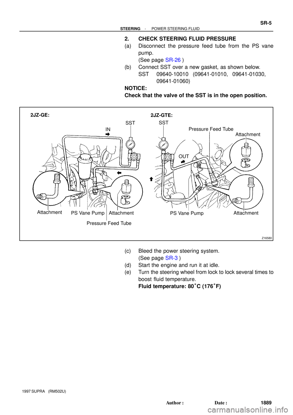
Z16580
INSSTSST
OUTPressure Feed Tube
Attachment
PS Vane Pump 2JZ-GE:
2JZ-GTE:
Attachment Attachment PS Vane Pump Attachment
Pressure Feed Tube
- STEERINGPOWER STEERING FLUID
SR-5
1889 Author�: Date�:
1997 SUPRA (RM502U)
2. CHECK STEERING FLUID PRESSURE
(a) Disconnect the pressure feed tube from the PS vane
pump.
(See page SR-26)
(b) Connect SST over a new gasket, as shown below.
SST 09640-10010 (09641-01010, 09641-01030,
09641-01060)
NOTICE:
Check that the valve of the SST is in the open position.
(c) Bleed the power steering system.
(See page SR-3)
(d) Start the engine and run it at idle.
(e) Turn the steering wheel from lock to lock several times to
boost fluid temperature.
Fluid temperature: 80°C (176°F)
Page 1575 of 1807

Z15498
PS GearOil
Reservior
PS Vane
Pump Closed
SST
Z15499
PS GearOil
Reservior
PS Vane
Pump
SST Open
Z15500
PS GearOil
Reservior
PS Vane
Pump
SST Open SR-6
- STEERINGPOWER STEERING FLUID
1890 Author�: Date�:
1997 SUPRA (RM502U)
(f) With the engine idling, close the valve of the SST and ob-
serve the reading on the SST.
Minimum fluid pressure:
7,355 kPa (75 kgf.cm
2, 1,067 psi)
NOTICE:
�Do not keep the valve closed for more than 10 se-
conds.
�Do not let the fluid temperature become too high.
(g) With the engine idling, open the valve fully.
(h) Measure the fluid pressure at engine speeds of 1,000 rpm
and 3,000 rpm.
Difference fluid pressure:
490 kPa (5 kgf.cm
2, 71 psi) or less
NOTICE:
Do not turn the steering wheel.
(i) With the engine idling and valve fully opened, turn the
wheel to full lock.
Minimum fluid pressure:
7,355 kpa (75 kgf,cm
2, 1,067 psi)
NOTICE:
�Do not maintain lock position for more than 10 se-
conds.
�Do not let the fluid temperature become too high.
(j) Disconnect the SST.
(k) Connect the pressure feed tube.
(See page SR-34)
(l) Bleed the power steering system.
(See page SR-3)
Page 1577 of 1807

STEERING WHEEL
INSPECTION
1. CHECK STEERING WHEEL FREEPLAY
With the vehicle stopp")
SR13W-01
R09732
W00625
PPS Solenoid
Connector SR-8
- STEERINGSTEERING WHEEL
1892 Author�: Date�:
1997 SUPRA (RM502U)
STEERING WHEEL
INSPECTION
1. CHECK STEERING WHEEL FREEPLAY
With the vehicle stopped and tires pointed straight ahead, rock
the steering wheel gently back and forth with light finger pres-
sure.
Freeplay should not exceed the maximum.
Maximum freeplay: 30 mm (1.18 in.)
2. CHECK STEERING EFFORT
(a) Center the steering wheel.
(b) Remove the steering wheel pad.
(See page SR-1 1)
(c) Start the engine and run it at idle.
(d) Measure the steering effort in both directions.
Reference (Maximum): 6.9 N´m (70 kgf´cm, 61 in.´lbf)
If steering effort is excessive, repair the power steering unit.
HINT:
Be sure to consider the tire type, pressure and contact surface
before making your diagnosis.
(e) Disconnect the PPS solenoid connector.
(f) Measure the steering effort in both directions and check
that the steering effort exceeds the reference value in (d),
and that the power assist is operating.
If steering effort is not heavier than (d), check the solenoid.
(g) Connect the connector.
(h) Torque the steering wheel set nut.
Torque: 35 N´m (360 kgf´cm, 26 ft´lbf)
(i) Install the steering wheel pad.
(See page SR-21)
Page 1592 of 1807
SR143-01
Z18268
2JZ-GE:
PS Vane Pump
AssemblyOil ReservoirReturn Tube
Battery Clamp
Battery Cover
� Terminal
� Terminal Pressure Feed Tube Air Control Valve
� Gasket
Union Bolt
Drive Belt
Battery
Battery Carrier
Engine Under Cover
x10
� Non-reusable part
- STEERINGPOWER STEERING VANE PUMP
SR-23
1907 Author�: Date�:
1997 SUPRA (RM502U)
POWER STEERING VANE PUMP
COMPONENTS
Page 1593 of 1807
Z18269
2JZ-GTE:
Battery Clamp
Battery Cover
� Terminal
� Terminal
Battery Pressure Feed Tube
� GasketUnion Bolt Drive Belt
Battery Carrier Air Hose No.5
Oil Reservoir to
Pump Hose
PS Vane Pump Assembly
Vane Pump Pulley
Engine Under Cover
x10
� Non-reusable part SR-24
- STEERINGPOWER STEERING VANE PUMP
1908 Author�: Date�:
1997 SUPRA (RM502U)
Page 1594 of 1807
Z19281
2JZ-GE and 2JZ-GTE:
Reservoir Cap2JZ-GE:
Oil Reservoir
2JZ-GTE:
Suction Port Union
� O-Ring
Flow Control Valve
Pressure Port
Union Front Housing
Vane Pump Shaft
2JZ-GE:
Vane Pump Pulley� O-Ring
� Bearing� Oil Seal� Gasket
Spring
� O-Ring
� Snap Ring
� Snap Ring
� O-Ring
� Straight Pin
Rear Housing Wave Washer
Side Plate
Cam Ring
Vane Plate Vane Pump Rotorx10
� Straight Pin
� Non-reusable part
: Power steering fluid
- STEERINGPOWER STEERING VANE PUMP
SR-25
1909 Author�: Date�:
1997 SUPRA (RM502U)
Page 1595 of 1807

REMOVAL
1. REMOVE ENGINE UNDER COVER
Remove the 10 screws.
2. REMOVE BATTERY
(a) Disco")
SR144-01
R06091
R07429
R07432
SR-26
- STEERINGPOWER STEERING VANE PUMP
1910 Author�: Date�:
1997 SUPRA (RM502U)
REMOVAL
1. REMOVE ENGINE UNDER COVER
Remove the 10 screws.
2. REMOVE BATTERY
(a) Disconnect the 2 terminals.
(b) Remove the bolt, nut and battery clamp.
(c) Remove the battery cover.
(d) Remove the battery and battery carrier.
3. 2JZ-GTE:
REMOVE AIR HOSE No.5
4. REMOVE DRIVE BELT
Loosen the drive belt tension by turning the drive belt tensioner
clockwise, and remove the drive belt.
5. 2JZ-GTE:
DISCONNECT OIL RESERVOIR TO PUMP HOSE
Remove the clip and disconnect the hose.
NOTICE:
Take care not to spill fluid on the A/C compressor rotor.
6. 2JZ-GE:
DISCONNECT RETURN TUBE
NOTICE:
Take care not to spill fluid on the A/C compressor rotor.
7. 2JZ-GTE:
REMOVE VANE PUMP PULLEY
Using SST to stop the pulley rotating, remove the nut.
SST 09960-10010 (09962-01000, 09963-01000)
8. REMOVE PRESSURE FEED TUBE
Using a spanner (24 mm) to hold the pressure port union, re-
move the union bolt and gasket.
9. REMOVE PS VANE PUMP ASSEMBLY
Remove the 2 pump assembly set bolts.