Page 1365 of 1807

S00263
S00268
SST
SST
P03960
A02559
SST
S00394
EM-22
- ENGINE MECHANICAL (2JZ-GTE)TIMING BELT
1127 Author�: Date�:
1997 SUPRA (RM502U)
4. INSTALL TIMING BELT GUIDE
Install the guide, facing the cup side outward.
5. INSTALL NO.1 TIMING BELT COVER
6. INSTALL CRANKSHAFT PULLEY
(a) Align the pulley set key with the key groove of the pulley,
and slide on the pulley.
(b) Using SST, install the bolt.
SST 09213-70010, 09330-00021
Torque: 324 N´m (3,300 kgf´cm, 239 ft´lbf)
7. A/T:
CONNECT OIL COOLER TUBES
8. INSTALL CAMSHAFT TIMING PULLEYS
(a) Align the camshaft knock pin with the groove of the pulley,
and slide on the timing pulley.
(b) Temporarily install the timing pulley bolt.
(c) Using SST, tighten the pulley bolt.
SST 09960-10010 (09962-01000, 09963-01000)
Torque: 79 N´m (810 kgf´cm, 59 ft´lbf)
9. SET NO.1 CYLINDER TO TDC/COMPRESSION
(a) Turn the crankshaft pulley, and align its groove with timing
mark º0º of the No.1 timing belt cover.
NOTICE:
Always turn the crankshaft clockwise.
Page 1366 of 1807

A02558SST
A02562
Z02446
1.5 mm
Hexagon
Wrench
P04459
P11756
- ENGINE MECHANICAL (2JZ-GTE)TIMING BELT
EM-23
1128 Author�: Date�:
1997 SUPRA (RM502U)
(b) Using SST, align the timing marks of the camshaft timing
pulleys and No.4 timing belt cover.
SST 09960-10010 (09962-01000, 09963-01000)
10. INSTALL TIMING BELT
HINT:
(When re-using timing belt):
Align the matchmarks of the timing belt and camshaft timing
pulleys.
(a) Remove any oil or water on the camshaft timing pulley,
and keep it clean.
(b) Install the timing belt, checking the tension between the
crankshaft timing pulley and exhaust camshaft timing
pulley.
11. SET TIMING BELT TENSIONER
(a) Using a press, slowly press in the push rod using 981 -
9,807 N (100 - 1,000 kgf, 220 - 2,205 lbf) of force.
(b) Align the holes of the push rod and housing, pass a 1.5
mm hexagon wrench through the holes to keep the push
rod retracted.
(c) Release the press.
(d) Install the dust boot onto the tensioner.
12. INSTALL TIMING BELT TENSIONER
(a) Temporarily install the tensioner with the 2 bolts.
(b) Alternately tighten the 2 bolts.
Torque: 26 N´m (270 kgf´cm, 20 ft´lbf)
Page 1367 of 1807
P02587
P02154
P11647
S00259
SST
A
BA EM-24
- ENGINE MECHANICAL (2JZ-GTE)TIMING BELT
1129 Author�: Date�:
1997 SUPRA (RM502U)
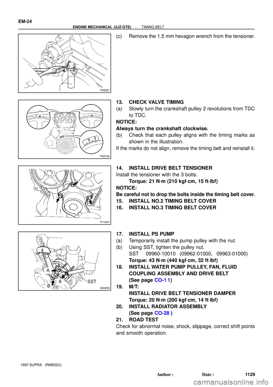
(c) Remove the 1.5 mm hexagon wrench from the tensioner.
13. CHECK VALVE TIMING
(a) Slowly turn the crankshaft pulley 2 revolutions from TDC
to TDC.
NOTICE:
Always turn the crankshaft clockwise.
(b) Check that each pulley aligns with the timing marks as
shown in the illustration.
If the marks do not align, remove the timing belt and reinstall it.
14. INSTALL DRIVE BELT TENSIONER
Install the tensioner with the 3 bolts.
Torque: 21 N´m (210 kgf´cm, 15 ft´lbf)
NOTICE:
Be careful not to drop the bolts inside the timing belt cover.
15. INSTALL NO.2 TIMING BELT COVER
16. INSTALL NO.3 TIMING BELT COVER
17. INSTALL PS PUMP
(a) Temporarily install the pump pulley with the nut.
(b) Using SST, tighten the pulley nut.
SST 09960-10010 (09962-01000, 09963-01000)
Torque: 43 N´m (440 kgf´cm, 32 ft´lbf)
18. INSTALL WATER PUMP PULLEY, FAN, FLUID
COUPLING ASSEMBLY AND DRIVE BELT
(See page CO-1 1)
19. M/T:
INSTALL DRIVE BELT TENSIONER DAMPER
Torque: 20 N´m (200 kgf´cm, 14 ft´lbf)
20. INSTALL RADIATOR ASSEMBLY
(See page CO-28)
21. ROAD TEST
Check for abnormal noise, shock, slippage, correct shift points
and smooth operation.
Page 1373 of 1807
LU04U-02
S00606
2JZ-GE
No.3 Timing Belt Cover
Oil Filler Cap
Crankshaft Position Sensor
Timing Belt
PlateOil Level Sensor
Connector
� Non-reusable partOil Dipstick and
Guide
Timing Belt
Oil Pan Baffle Plate Oil Level SensorNo.1 Oil Pan
Oil Strainer
No.2 Oil Pan Timing Belt Guide
No.1 Timing Belt Cover
Crankshaft Pulley No.2 Timing
Belt Cover
Drive Belt
Tensioner� O-Ring x 9
� Gasket � Crankshaft Front Oil Seal
� Precoated partOil Pump
Crankshaft Timing Pulley
Gasket
x 16
x 5
x 16
� Gasket Generator
� O-Ring� O-Ring
� Gasket Idler Pulley
�
x 6
x 5
Dust Boot
Timing Belt Tensionerx 6
Gasket LU-6
- LUBRICATIONOIL PUMP
1453 Author�: Date�:
1997 SUPRA (RM502U)
OIL PUMP
COMPONENTS
Page 1374 of 1807
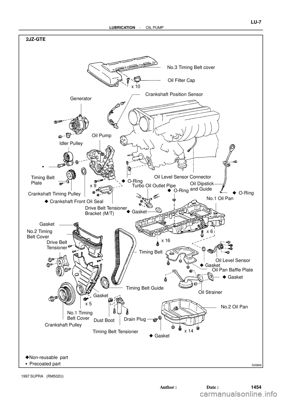
S00866
No.3 Timing Belt cover
Crankshaft Position Sensor
Oil Level Sensor ConnectorOil Filter Cap
Generator
Oil Strainer Oil Pump
� O-Ring
Turbo Oil Outlet Pipe Timing Belt
Plate
Crankshaft Timing Pulley
� Crankshaft Front Oil SealNo.1 Oil Pan Idler Pulley
� O-Ring �
Drive Belt Tensioner
Bracket (M/T)
Timing Belt GuideOil Level Sensor
� Gasket
Timing Belt Tensioner No.1 Timing
Belt Cover
Crankshaft PulleyDust BootDrain Plug
� GasketNo.2 Oil Pan
�Non-reusable part
�Precoated part� O-Ring
� Gasket
Timing Belt x 10
Oil Pan Baffle Plate Oil Dipstick
and Guide
Gasket
No.2 Timing
Belt Cover
Drive Belt
Tensionerx 6
x 5
x 14 x 16 2JZ-GTE
Gasket x 9
� Gasket
- LUBRICATIONOIL PUMP
LU-7
1454 Author�: Date�:
1997 SUPRA (RM502U)
Page 1376 of 1807
LU0K0-01
P11911
- LUBRICATIONOIL PUMP
LU-9
1456 Author�: Date�:
1997 SUPRA (RM502U)
REMOVAL
HINT:
When repairing the oil pump, the oil pan and strainer should be
removed and cleaned.
1. REMOVE ENGINE WITH TRANSMISSION
(2JZ-GE: See page EM-57)
(2JZ-GTE: See page EM-58)
2. SEPARATE ENGINE AND TRANSMISSION
(2JZ-GE: See page AT-20)
(2JZ-GTE: See page EM-58)
3. INSTALL ENGINE TO ENGINE STAND FOR REMOVAL
4. REMOVE GENERATOR (See page CH-8)
5. REMOVE CRANKSHAFT POSITION SENSOR
(a) Disconnect the sensor connector from the clamp bracket.
(b) Disconnect the sensor connector from the wiring connec-
tor.
(c) 2JZ-GTE:
Disconnect the wire clamp from the cylinder block.
(d) Remove the bolt and position sensor.
6. REMOVE TIMING BELT
(2JZ-GE: See page EM-13)
(2JZ-GTE: See page EM-15)
7. 2JZ-GTE M/T:
REMOVE DRIVE BELT TENSIONER BRACKET
Remove the 2 nuts and tensioner bracket.
8. REMOVE IDLER PULLEY AND CRANKSHAFT TIMING
PULLEY
(2JZ-GE: See page EM-13)
(2JZ-GTE: See page EM-15)
9. REMOVE OIL DIPSTICK AND GUIDE
(a) Remove the bolt.
(b) Pull out the dipstick guide together with the dipstick.
(c) Remove the O-ring from the dipstick guide.
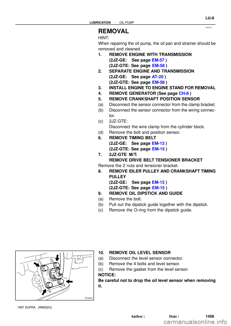
10. REMOVE OIL LEVEL SENSOR
(a) Disconnect the level sensor connector.
(b) Remove the 4 bolts and level sensor.
(c) Remove the gasket from the level sensor.
NOTICE:
Be careful not to drop the oil level sensor when removing
it.
Page 1384 of 1807
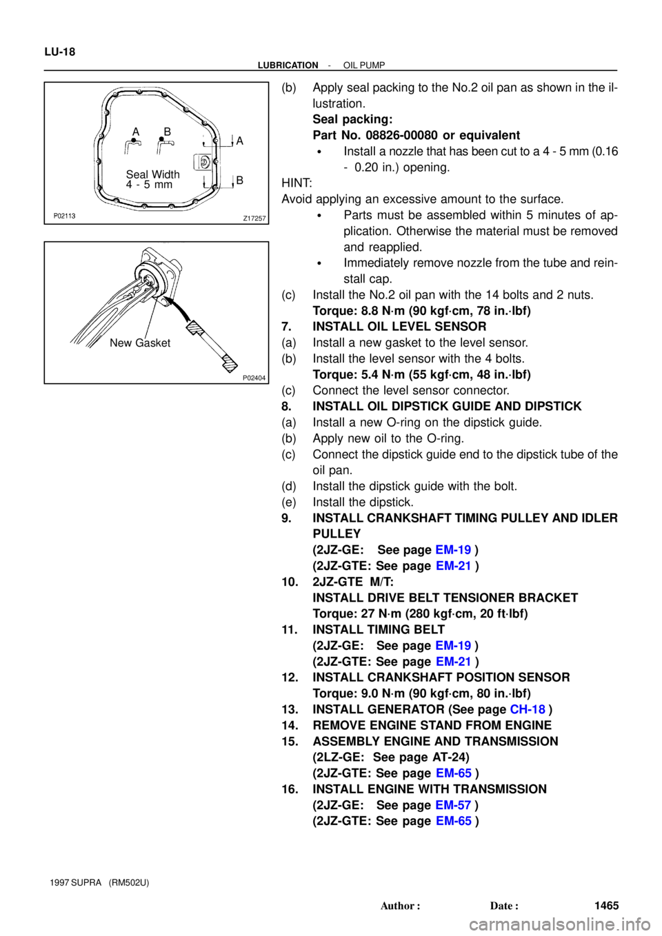
Z17257
Seal WidthAB
4 - 5 mmA
B
P02404
New Gasket LU-18
- LUBRICATIONOIL PUMP
1465 Author�: Date�:
1997 SUPRA (RM502U)
(b) Apply seal packing to the No.2 oil pan as shown in the il-
lustration.
Seal packing:
Part No. 08826-00080 or equivalent
�Install a nozzle that has been cut to a 4 - 5 mm (0.16
- 0.20 in.) opening.
HINT:
Avoid applying an excessive amount to the surface.
�Parts must be assembled within 5 minutes of ap-
plication. Otherwise the material must be removed
and reapplied.
�Immediately remove nozzle from the tube and rein-
stall cap.
(c) Install the No.2 oil pan with the 14 bolts and 2 nuts.
Torque: 8.8 N´m (90 kgf´cm, 78 in.´lbf)
7. INSTALL OIL LEVEL SENSOR
(a) Install a new gasket to the level sensor.
(b) Install the level sensor with the 4 bolts.
Torque: 5.4 N´m (55 kgf´cm, 48 in.´lbf)
(c) Connect the level sensor connector.
8. INSTALL OIL DIPSTICK GUIDE AND DIPSTICK
(a) Install a new O-ring on the dipstick guide.
(b) Apply new oil to the O-ring.
(c) Connect the dipstick guide end to the dipstick tube of the
oil pan.
(d) Install the dipstick guide with the bolt.
(e) Install the dipstick.
9. INSTALL CRANKSHAFT TIMING PULLEY AND IDLER
PULLEY
(2JZ-GE: See page EM-19)
(2JZ-GTE: See page EM-21)
10. 2JZ-GTE M/T:
INSTALL DRIVE BELT TENSIONER BRACKET
Torque: 27 N´m (280 kgf´cm, 20 ft´lbf)
11. INSTALL TIMING BELT
(2JZ-GE: See page EM-19)
(2JZ-GTE: See page EM-21)
12. INSTALL CRANKSHAFT POSITION SENSOR
Torque: 9.0 N´m (90 kgf´cm, 80 in.´lbf)
13. INSTALL GENERATOR (See page CH-18)
14. REMOVE ENGINE STAND FROM ENGINE
15. ASSEMBLY ENGINE AND TRANSMISSION
(2LZ-GE: See page AT-24)
(2JZ-GTE: See page EM-65)
16. INSTALL ENGINE WITH TRANSMISSION
(2JZ-GE: See page EM-57)
(2JZ-GTE: See page EM-65)
Page 1394 of 1807
EM0AD-02
Z16754
M/T
Z16759
P19042
5 mm Hexagon Wrench
P12535
- ENGINE MECHANICAL (2JZ-GTE)TIMING BELT
EM-15
1120 Author�: Date�:
1997 SUPRA (RM502U)
REMOVAL
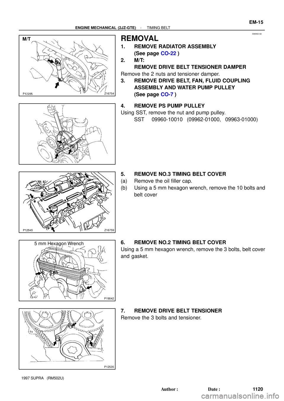
1. REMOVE RADIATOR ASSEMBLY
(See page CO-22)
2. M/T:
REMOVE DRIVE BELT TENSIONER DAMPER
Remove the 2 nuts and tensioner damper.
3. REMOVE DRIVE BELT, FAN, FLUID COUPLING
ASSEMBLY AND WATER PUMP PULLEY
(See page CO-7)
4. REMOVE PS PUMP PULLEY
Using SST, remove the nut and pump pulley.
SST 09960-10010 (09962-01000, 09963-01000)
5. REMOVE NO.3 TIMING BELT COVER
(a) Remove the oil filler cap.
(b) Using a 5 mm hexagon wrench, remove the 10 bolts and
belt cover
6. REMOVE NO.2 TIMING BELT COVER
Using a 5 mm hexagon wrench, remove the 3 bolts, belt cover
and gasket.
7. REMOVE DRIVE BELT TENSIONER
Remove the 3 bolts and tensioner.