Page 587 of 1807
BE6653
P24310A00099
ON
1(+)
A00689
STARTCheck Harness A
ECM
B66 VG(+)
DI-172
- DIAGNOSTICSENGINE (2JZ-GTE)
400 Author�: Date�:
1997 SUPRA (RM502U)
2 Check voltage of mass air flow meter power source.
PREPARATION:
(a) Disconnect the mass air flow meter connector.
(b) Turn ignition switch ON.
CHECK:
Measure voltage between terminal 1 of mass air flow meter con-
nector and body ground.
OK:
Voltage: 9 - 14 V
NG Check for open in harness and connector be-
tween EFI main relay (Marking: EFI MAIN) and
mass air flow meter (See page IN-28).
OK
3 Check voltage between terminal VG of ECM and body ground.
PREPARATION:
(a) Connect Check Harness A (See page DI-164).
(b) Start the engine.
CHECK:
Measure voltage between terminal VG of ECM and body
ground while engine is idling, transmission is in park or neutral
position and A/C switch is OFF.
OK:
Voltage: 1.1 - 1.5 V
OK Check and replace ECM (See page IN-28).
NG
Page 588 of 1807
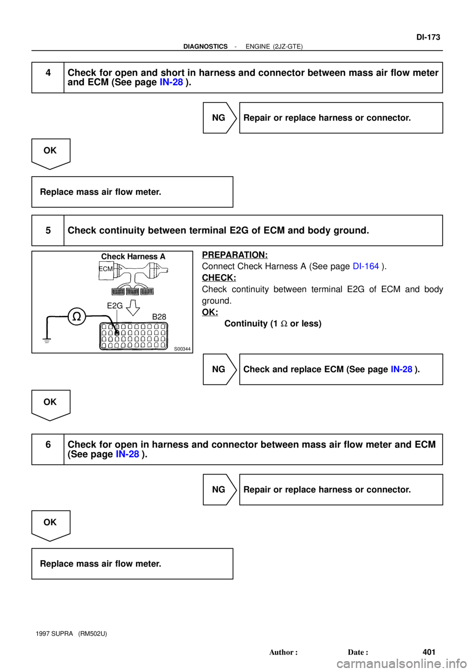
S00344
Check Harness A
ECM
B28 E2G
- DIAGNOSTICSENGINE (2JZ-GTE)
DI-173
401 Author�: Date�:
1997 SUPRA (RM502U)
4 Check for open and short in harness and connector between mass air flow meter
and ECM (See page IN-28).
NG Repair or replace harness or connector.
OK
Replace mass air flow meter.
5 Check continuity between terminal E2G of ECM and body ground.
PREPARATION:
Connect Check Harness A (See page DI-164).
CHECK:
Check continuity between terminal E2G of ECM and body
ground.
OK:
Continuity (1 W or less)
NG Check and replace ECM (See page IN-28).
OK
6 Check for open in harness and connector between mass air flow meter and ECM
(See page IN-28).
NG Repair or replace harness or connector.
OK
Replace mass air flow meter.
Page 589 of 1807
DI-174
- DIAGNOSTICSENGINE (2JZ-GTE)
402 Author�: Date�:
1997 SUPRA (RM502U)
DTC P0101 Mass Air Flow Circuit Range / Performance
Problem
CIRCUIT DESCRIPTION
Refer to ºMass Air Flow Circuit Malfunctionº on page DI-170.
DTC No.DTC Detecting ConditionTrouble Area
P0101
Conditions (a), (b) and (c) continue with engine speed 900
rpm or less:
(2 trip detection logic)
(a) Closed throttle position switch: ON
(b) Mass air flow meter output > 2.2 V
(c) Engien coolant temp. � 70°C
�Mass air flow meterP0101
Conditions (a) and (b) continue with engine speed 1,500 rpm or
more:
(2 trip detection logic)
(a) Mass air flow meter output < 1.0 V
(b) VTA � 0.72 V
�Mass air flow meter
WIRING DIAGRAM
Refer to page DI-170 or the WARNING DIAGRAM.
INSPECTION PROCEDURE
1 Are there any other codes (besides DTC P0101) being output?
YES Go to relevant DTC chart.
NO
Replace mass air flow meter.
DI4SN-01
Page 590 of 1807
 (32) (68)(104)(140)(176)(212)
Temperature °C (°F) 0.1 0.20.3 0.51 2 35 10 2030
- DIAGNOSTICSENGINE (2JZ-GTE)
DI-175
403 Author�: Date�:
199")
FI4741
Acceptable
Resistance kW
-20 0
20 40 60 80 100
(-4) (32) (68)(104)(140)(176)(212)
Temperature °C (°F) 0.1 0.20.3 0.51 2 35 10 2030
- DIAGNOSTICSENGINE (2JZ-GTE)
DI-175
403 Author�: Date�:
1997 SUPRA (RM502U)
DTC P0110 Intake Air Temp. Circuit Malfunction
CIRCUIT DESCRIPTION
The intake air temperature sensor is built into the air flow meter
and senses the intake air temperature.
A thermistor built in the sensor changes the resistance value
according to the intake air temperature.
The lower the intake air temperature, the greater the thermistor
resistance value, and the higher the intake air temperature, the
lower the thermistor resistance value (See Fig. 1).
The intake air temperature sensor is connected to the ECM.
The 5 V power source voltage in the ECM is applied to the in-
take air temperature sensor from the terminal THA via a resistor
R.
That is , the resistor R and the intake air temperature sensor are
connected in series. When the resistance value of the intake air
temperature sensor changes in accordance with changes in the
intake air temperature, the potential at terminal THA also
changes. Based on this signal, the ECM increases the fuel in-
jection volume to improve driveability during cold engine opera-
tion.
If the ECM detects the DTC ºP0110º, it operates the fail safe
function in which the intake air temperature is assumed to be
20°C (68°F).
Intake Air Temp. °C (°F)Resistance (kW)Voltage (V)
-20 (-4)16.24.3
0 (32)5.93.4
20 (68)2.52.4
40 (104)1.11.4
60 (140)0.60.9
80 (176)0.30.5
100 (212)0.10.2
DTC No.DTC Detecting ConditionTrouble Area
P0110Open or short in intake air temp. sensor circuit
�Open or short in intake air temp. sensor circuit
�Intake air temp. sensor
�ECM
HINT:
After confirming DTC P0110 use the OBD II scan tool or TOYOTA hand-held tester to confirm the intake
air temperature from ºCURRENT DATAº.
Temperature DisplayedMalfunction
- 40°C (- 40°F)Open circuit
140°C (284°F) or moreShort circuit
DI4SO-01
Page 591 of 1807

3
4P-L
W-B45
65B
BECM
5V
THAR
E2
E2
DI-176
- DIAGNOSTICSENGINE (2JZ-GTE)
404 Author�: Date�:
1997 SUPRA (RM502U)
WIRING DIAGRAM
INSPEC")
FI6448
Intake Air Temp. Sensor
(Inside the mass air flow meter)
3
4P-L
W-B45
65B
BECM
5V
THAR
E2
E2
DI-176
- DIAGNOSTICSENGINE (2JZ-GTE)
404 Author�: Date�:
1997 SUPRA (RM502U)
WIRING DIAGRAM
INSPECTION PROCEDURE
HINT:
�If DTC ºP0110º (Intake Air Temp. Circuit Malfunction), ºP0115º (Engine Coolant Temp. Circuit Malfunc-
tion), ºP0120º (Throttle/Pedal Position Sensor/Switch ºAº Circuit Malfunction), are output simulta-
neously, E2 (sensor ground) may be open.
1 Connect the OBD II scan tool or TOYOTA hand-held tester, and read value of in-
take air temperature.
PREPARATION:
(a) Connect the OBD II scan tool or TOYOTA hand-held tester to the DLC3.
(b) Turn ignition switch ON and push the OBD II scan tool or TOYOTA hand-held tester main switch ON.
CHECK:
Read temperature value on the OBD II scan tool or TOYOTA hand-held tester.
OK:
Same as actual intake air temperature.
HINT:
�If there is open circuit, OBD II scan tool or TOYOTA hand-held tester indicates - 40°C (- 40°F).
�If there is short circuit, OBD II scan tool or TOYOTA hand-held tester indicates 140°C (284°F) or more.
NG - 40 °C (- 40 °F) ............. Go to step 2.
140 °C (284 °F) or more .. Go to step 4.
OK
Check for intermittent problems.
(See page DI-147)
Page 592 of 1807

D")
BE6653
A00347
A00348
ON
Intake Air
Temp. Sensor
3
4ECM
5V
THA
E2 B
B 45
65
A00690
ON
Intake Air
Temp. Sensor3
445
65
B
B
ECM
5V
THA
E2
Check Harnss A
B45, 65
THA
E2
ECM
- DIAGNOSTICSENGINE (2JZ-GTE)
DI-177
405 Author�: Date�:
1997 SUPRA (RM502U)
2 Check for open in harness or ECM.
PREPARATION:
(a) Disconnect the mass air flow meter connector.
(b) Connect sensor wire harness terminals together.
(c) Turn ignition switch ON.
CHECK:
Read temperature value on the OBD II scan tool or TOYOTA
hand-held tester.
OK:
Temperature value: 140°C (284°F) or more
OK Confirm good connection at sensor.
If OK, replace mass air flow meter.
NG
3 Check for open in harness or ECM.
PREPARATION:
(a) Connect Check Harness A (See page DI-164).
(b) Connect between terminals THA and E2 of ECM connec-
tor.
HINT:
Mass air flow meter connector is disconnected. Before check-
ing, do a visual and contact pressure check for the ECM con-
nector (See page IN-28).
(c) Turn ignition switch ON.
CHECK:
Read temperature value on the OBD II scan tool or TOYOTA
hand-held tester.
OK:
Temperature value: 140°C (284°F) or more
OK Open in harness between terminals E2 or THA,
repair or replace harness.
NG
Confirm good connection at ECM.
If OK, replace ECM.
Page 593 of 1807
A00393
ON
3
445
65
B
B
ECM
5V
THA
E2 Intake Air
Temp. Sensor
A00691
ON
ECM
5V
THA
E2 Intake Air
Temp. Sensor
ECM
B Connector
DI-178
- DIAGNOSTICSENGINE (2JZ-GTE)
406 Author�: Date�:
1997 SUPRA (RM502U)
4 Check for short in harness and ECM.
PREPARATION:
(a) Disconnect the mass air flow meter connector.
(b) Turn ignition switch ON.
CHECK:
Read temperature value on the OBD II scan tool or TOYOTA
hand-held tester.
OK:
Temperature value: - 40°C (- 40°F).
OK Replace mass air flow meter.
NG
5 Check for short in harness or ECM.
PREPARATION:
(a) Disconnect the B connector from ECM
(See page DI-164).
HINT:
Mass air flow meter connector is disconnected.
(b) Turn ignition switch ON.
CHECK:
Read temperature value on the OBD II scan tool or TOYOTA
hand-held tester.
OK:
Temperature value: - 40°C (- 40°F)
OK Repair or replace harness or connector.
NG
Check and replace ECM (See page IN-28).
Page 594 of 1807

DI-179
407 Author�: Date�:
1997 SUPRA (RM502U)
DTC P0115 Engine Coolant Temp. Circuit Malfunction
CIRC")
P19603
Engine Coolant Temp. SensorECM
2
1L-Y
W-B44
65B
BTHW
E2R5V
- DIAGNOSTICSENGINE (2JZ-GTE)
DI-179
407 Author�: Date�:
1997 SUPRA (RM502U)
DTC P0115 Engine Coolant Temp. Circuit Malfunction
CIRCUIT DESCRIPTION
A thermistor built into the engine coolant temperature sensor changes the resistance value according to the
engine coolant temperature.
The structure of the sensor and connection to the ECM is the same as in the intake air temperature circuit
malfunction shown on page DI-175.
If the ECM detects the DTC P0115, it operates the fail safe function in which the engine coolant temperature
is assumed to be 80°C (176°F).
DTC No.DTC Detecting ConditionTrouble Area
P0115Open or short in engine coolant temp. sensor circuit
�Open or short in engine coolant temp. sensor circuit
�Engine coolant temp. sensor
�ECM
HINT:
After confirming DTC P0115 use the OBD II scan tool or TOYOTA hand-held tester to confirm the engine
coolant temperature from ºCURRENT DATAº.
Temperature DisplayedMalfunction
- 40°C (- 40°F)Open circuit
140°C (284°F) or moreShort circuit
WIRING DIAGRAM
DI4SP-01