Page 595 of 1807

408 Author�: Date�:
1997 SUPRA (RM502U)
INSPECTION PROCEDURE
HINT:
�If DTC ºP0110º (")
BE6653FI7057A06715
ON
Engine Coolant
Temp. Sensor
2
144
65ECM
5V
THW
E2
BB
DI-180
- DIAGNOSTICSENGINE (2JZ-GTE)
408 Author�: Date�:
1997 SUPRA (RM502U)
INSPECTION PROCEDURE
HINT:
�If DTC ºP0110º (Intake Air Temp. Circuit Malfunction), ºP0115º (Engine Coolant Temp. Circuit Malfunc-
tion), ºP0120º (Throttle/Pedal Position Sensor/Switch ºAº Circuit Malfunction) are output simulta-
neously, E2 (sensor ground) may be open.
1 Connect the OBD II scan tool or TOYOTA hand-held tester, and read value of en-
gine coolant temperature.
PREPARATION:
(a) Connect the OBD II scan tool or TOYOTA hand-held tester to the DLC3.
(b) Turn ignition switch ON and push the OBD II scan tool or TOYOTA hand-held tester main switch ON.
CHECK:
Read temperature value on the OBD II scan tool or TOYOTA hand-held tester.
OK:
Same as actual engine coolant temperature.
HINT:
�If there is open circuit, OBD II scan tool or TOYOTA hand-held tester indicates - 40°C (- 40°F).
�If there is short circuit, OBD II scan tool or TOYOTA hand-held tester indicates 140°C (284°F) or more.
NG - 40°C ( - 40°F) .............. Go to step 2.
140°C (284°F) or more .... Go to step 4.
OK
Check for intermittent problems
(See page DI-147).
2 Check for open in harness or ECM.
PREPARATION:
(a) Disconnect the engine coolant temp. sensor connector.
(b) Connect sensor wire harness terminals together.
(c) Turn ignition switch ON.
CHECK:
Read temperature value on the OBD II scan tool or TOYOTA
hand-held tester.
OK:
Temperature value: 140°C (284°F) or more
OK Confirm good connection at sensor. If OK,
replace engine coolant temp. sensor.
NG
Page 596 of 1807

BE6653FI7055P23923A06716
ON
Engine Coolant
Temp. Sensor
2
144
65ECM
5V
THW
E2
BB
Check Harness A
ECM
B65, 44
THW
E2
A00216
ON
Engine Coolant
Temp. SenosrECM
44
655V
THW
E2
BB
- DIAGNOSTICSENGINE (2JZ-GTE)
DI-181
409 Author�: Date�:
1997 SUPRA (RM502U)
3 Check for open in harness or ECM.
PREPARATION:
(a) Connect Check Harness A (See page DI-164).
(b) Connect between terminals THW and E2 of ECM connec-
tor.
HINT:
Engine coolant temp. sensor connector is disconnected. Be-
fore checking, do a visual and contact pressure check for the
ECM connector (See page IN-28).
(c) Turn ignition switch ON.
CHECK:
Read temperature value on the OBD II scan tool or TOYOTA
hand-held tester.
OK:
Temperature value: 140°C (284°F) or more
OK Open in harness between terminals E2 or THW,
repair or replace harness.
NG
Confirm good connection at ECM.
If OK, replace ECM.
4 Check for short in harness and ECM.
PREPARATION:
(a) Disconnect the engine coolant temp. sensor connector.
(b) Turn ignition switch ON.
CHECK:
Read temperature value on the OBD II scan tool or TOYOTA
hand-held tester.
OK:
Temperature value: - 40°C (- 40°F)
OK Replace engine coolant temp. sensor.
NG
Page 597 of 1807
BE6653FI7056P25067A06717
ON
Engine Coolant
Temp. SensorECM
5V
THW
E2
ECM
B Connector
DI-182
- DIAGNOSTICSENGINE (2JZ-GTE)
410 Author�: Date�:
1997 SUPRA (RM502U)
5 Check for short in harness or ECM.
PREPARATION:
(a) Disconnect the B connector of ECM (See page DI-164).
HINT:
Engine coolant temp. sensor connector is disconnected.
(b) Turn ignition switch ON.
CHECK:
Read temperature value on the OBD II scan tool or TOYOTA
hand-held tester.
OK:
Temperature value: - 40°C (- 40°F)
OK Repair or replace harness or connector.
NG
Check and replace ECM (See page IN-28).
Page 598 of 1807

DI-183
411 Author�: Date�:
1997 SUPRA (RM502U)
DTC P0116 Engine Coolant Temp. Circuit Range/
Performance Problem
CIRCUIT DESCRIPTION
Refer to ºEngine Coolant Temp. Cir")
- DIAGNOSTICSENGINE (2JZ-GTE)
DI-183
411 Author�: Date�:
1997 SUPRA (RM502U)
DTC P0116 Engine Coolant Temp. Circuit Range/
Performance Problem
CIRCUIT DESCRIPTION
Refer to ºEngine Coolant Temp. Circuit Malfunctionº on page DI-179.
DTC No.DTC Detecting ConditionTrouble Area
When the engine starts, the water temp. is -7°C (20°F) or
less. And, 20 min. or more after the engine starts, the engine
coolant temp. sensor value is 20°C (68°F) or less
(2 trip detection logic)
P0116
When the engine starts, the water temp. is between -7°C
(20°F) and 10°C (50°F). And, 5 min. or more after the engine
starts, the engine coolant temp. sensor value is 20°C (68°F) or
less
(2 trip detection logic)
�Engine coolant temp. sensor
�Cooling system
When the engine starts, the water temp. is 10°C (50°F) or
more. And, 2 min. or more after the engine starts, the engine
coolant temp. sensor value is 20°C (68°F) or less
(2 trip detection logic)
INSPECTION PROCEDURE
HINT:
If DTC ºP0115º (Engine Coolant Temp. Circuit Malfunction) and ºP0116º (Engine Coolant Temp. Circuit
Range/Performance) are output simultaneously, engine coolant temp. sensor circuit may be open.
Perform troubleshooting of DTC P0115 first.
1 Are there any other codes (besides DTC P0116) being output?
YES Go to relevant DTC chart.
NO
2 Check thermostat (See page CO-15).
NG Replace thermostat.
OK
Replace engine coolant temp. sensor.
DI4SQ-01
Page 599 of 1807

412 Author�: Date�:
1997 SUPRA (RM502U)
DTC P0120 Throttle/Pedal Position Sensor/Switch ºAº
Circuit Ma")
FI6480
Throttle Position
SensorECM
VCC
VTA1
IDL1
E25V
B+ DI-184
- DIAGNOSTICSENGINE (2JZ-GTE)
412 Author�: Date�:
1997 SUPRA (RM502U)
DTC P0120 Throttle/Pedal Position Sensor/Switch ºAº
Circuit Malfunction
CIRCUIT DESCRIPTION
The throttle position sensor is mounted in the throttle body and
detects the throttle valve opening angle. When the throttle valve
is fully closed, the IDL1 contacts in the throttle position sensor
are on, so the voltage at the terminal IDL1 of the ECM becomes
0 V. At this time, a voltage of approximately 0.7 V is applied to
terminal VTA1 of the ECM. When the throttle valve is opened,
the IDL1 contacts go off and thus the power source voltage of
approximately 12 V in the ECM is applied to the terminal IDL1
of the ECM. The voltage applied to the terminal VTA1 of the
ECM increases in proportion to the opening angle of the throttle
valve and becomes approximately 3.2 - 4.9 V when the throttle
valve is fully opened. The ECM judges the vehicle driving condi-
tions from these signals input from terminals VTA1 and IDL1,
and uses them as one of the conditions for deciding the air-fuel
ratio correction, power increases correction and fuel-cut con-
trol etc.
DTC No.DTC Detecting ConditionTrouble Area
P0120
Condition (a) or (b) conditions:
(a) VTA < 0.25 V, and closed throttle position switch is OFF
(b) VTA > 4.9 V�Open or short in throttle position sensor circuit
�Throttle position sensor
�ECM
HINT:
�If there is open circuit in IDL line, DTC P0120 does not indicate.
�After confirming DTC P0120 use the OBD II scan tool or TOYOTA hand-held tester to confirm the
throttle valve opening percentage and closed throttle position switch condition.
Throttle valve opening position expressed as percentageTblAThrottle valve fully closedThrottle valve fully openTrouble Area
0 %0 %VC line open
VTA1 line open or short
Approx. 100 %Approx. 100 %E2 line open
DI4SR-01
Page 600 of 1807
FI6879
Throttle Position Sensor
43 2 1L-R
Y
R
W-BB
B
B
B 41
43
64
65VCC
VTA1
IDL1
E2
E1B+ 5V ECM
4
3
2
1 Sub Throttle Position Sensor
L-R
Y-L
GR-R
W-BB 63B 42
VTA2
IDL2
E1B+ 5V
- DIAGNOSTICSENGINE (2JZ-GTE)
DI-185
413 Author�: Date�:
1997 SUPRA (RM502U)
WIRING DIAGRAM
Page 601 of 1807

DI-186
- DIAGNOSTICSENGINE (2JZ-GTE)
414 Author�: Date�:
1997 SUPRA (RM502U)
INSPECTION PROCEDURE
HINT:
If DTC P0110, P0115 and P0120 are output simultaneously, E2 (sensor grou")
FI7052
A00694
ON
1(+)
DI-186
- DIAGNOSTICSENGINE (2JZ-GTE)
414 Author�: Date�:
1997 SUPRA (RM502U)
INSPECTION PROCEDURE
HINT:
If DTC P0110, P0115 and P0120 are output simultaneously, E2 (sensor ground) may be open.
1 Connect the OBD II scan tool or TOYOTA hand-held tester and read the throttle
valve opening percentage.
PREPARATION:
(a) Connect the OBD II scan tool or TOYOTA hand-held tester to the DLC 3.
(b) Turn ignition switch ON and push the OBD II scan tool or TOYOTA hand-held tester main switch ON.
CHECK:
Read the throttle valve opening percentage.
OK:
Throttle valveThrottle valve opening position ex-
pressed as percentage
Fully openApprox. 70 %
Fully closedApprox. 10 %
OK Check for intermittent problems
(See page DI-147).
NG
2 Check voltage between terminal 1 of wire harness side connector and body
ground.
PREPARATION:
(a) Disconnect the throttle position sensor connector.
(b) Turn ignition switch ON.
CHECK:
Measure voltage between terminal 1 of wire harness side con-
nector and body ground.
OK:
Voltage: 4.5 - 5.5 V
NG Go to step 5.
OK
Page 602 of 1807
P24693
4
2
1
A00695
ONCheck Harness A
ECM
B65, 43
VTA1 (+)
E2 (-)
- DIAGNOSTICSENGINE (2JZ-GTE)
DI-187
415 Author�: Date�:
1997 SUPRA (RM502U)
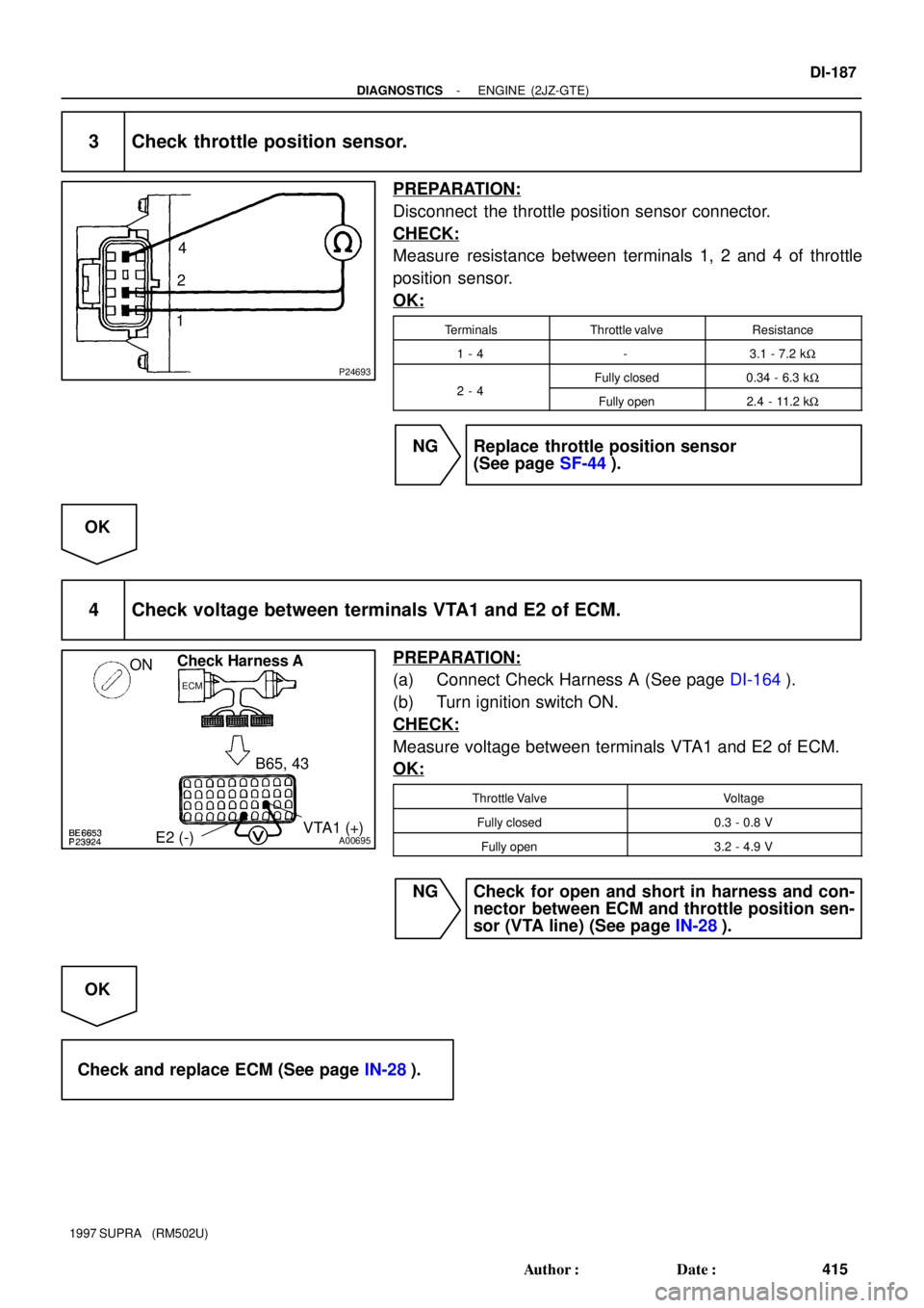
3 Check throttle position sensor.
PREPARATION:
Disconnect the throttle position sensor connector.
CHECK:
Measure resistance between terminals 1, 2 and 4 of throttle
position sensor.
OK:
TerminalsThrottle valveResistance
1 - 4-3.1 - 7.2 kW
24Fully closed0.34 - 6.3 kW2 - 4Fully open2.4 - 11.2 kW
NG Replace throttle position sensor
(See page SF-44).
OK
4 Check voltage between terminals VTA1 and E2 of ECM.
PREPARATION:
(a) Connect Check Harness A (See page DI-164).
(b) Turn ignition switch ON.
CHECK:
Measure voltage between terminals VTA1 and E2 of ECM.
OK:
Throttle ValveVoltage
Fully closed0.3 - 0.8 V
Fully open3.2 - 4.9 V
NG Check for open and short in harness and con-
nector between ECM and throttle position sen-
sor (VTA line) (See page IN-28).
OK
Check and replace ECM (See page IN-28).