Page 2617 of 3342

for at least one minute.
B4M0082D
D: TROUBL")
C: INSPECTION MODE
Reproduce the condition under which the problem has
occurred as much as possible.
Drive the vehicle at a speed more than 40 km/h (25 MPH)
for at least one minute.
B4M0082D
D: TROUBLE CODES
When on-board diagnosis of the ABS control module
detects a problem, the information (up to a maximum of
three) will be stored in the EEP ROM as a trouble code.
When there are more than three, the most recent three will
be stored. (Stored codes will stay in memory until they are
cleared.)
1. CALLING UP A TROUBLE CODE
1) Take out diagnosis connector from side of driver’s seat
heater unit.
2) Turn ignition switch OFF.
3) Connect diagnosis connector terminal 6 to diagnosis
terminal.
4) Turn ignition switch ON.
5) ABS warning light is set in the diagnostic mode and
blinks to identify trouble code.
6) After the start code (11) is shown, the trouble codes will
be shown in order of the last information first.
These repeat for a maximum of 5 minutes.
NOTE:
When there are no trouble codes in memory, only the start
code (11) is shown.
B4M0232A
12
4-4cBRAKES [ABS 5.3 TYPE]
6. Diagnostics Chart for On-board Diagnosis System
Page 2619 of 3342
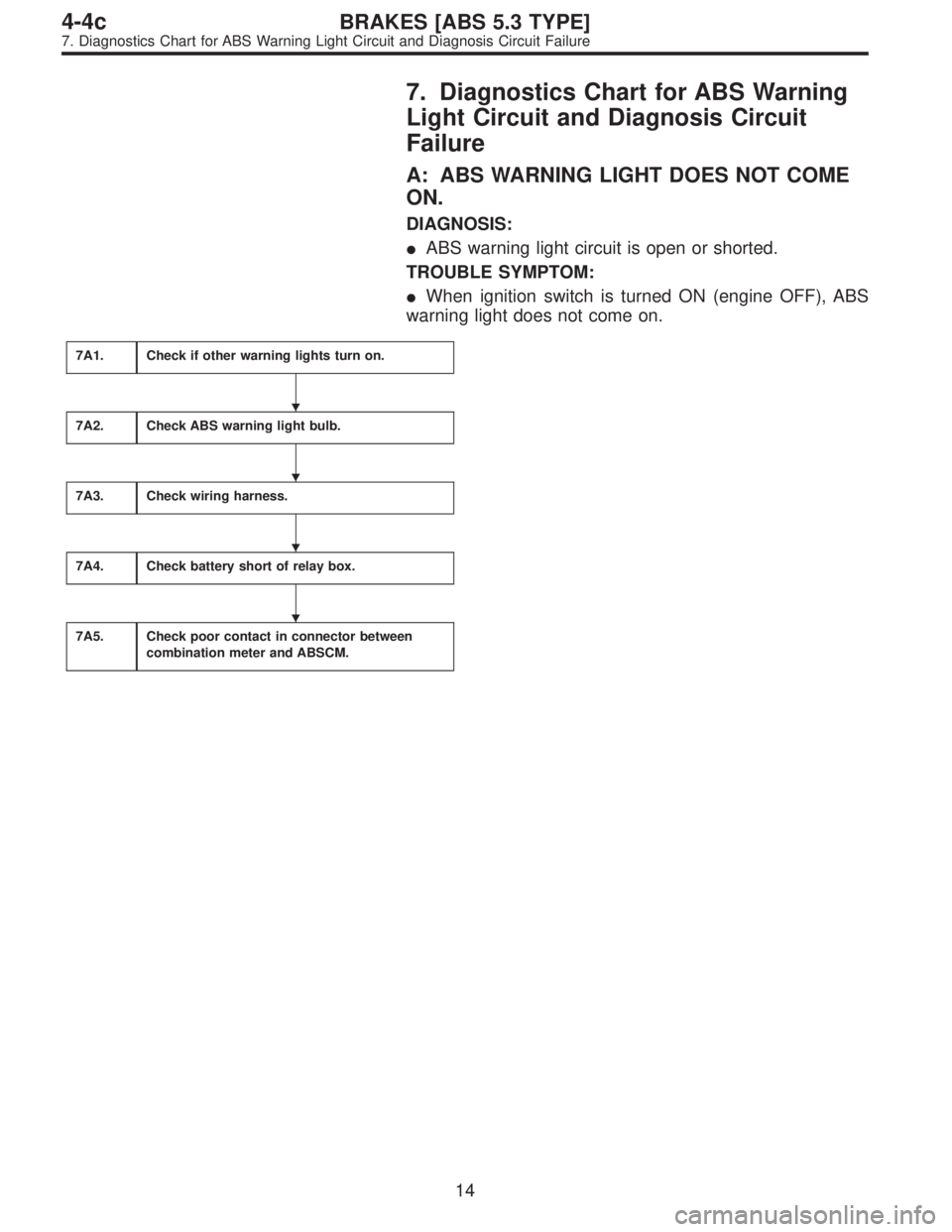
7. Diagnostics Chart for ABS Warning
Light Circuit and Diagnosis Circuit
Failure
A: ABS WARNING LIGHT DOES NOT COME
ON.
DIAGNOSIS:
�ABS warning light circuit is open or shorted.
TROUBLE SYMPTOM:
�When ignition switch is turned ON (engine OFF), ABS
warning light does not come on.
7A1.Check if other warning lights turn on.
7A2.Check ABS warning light bulb.
7A3.Check wiring harness.
7A4.Check battery short of relay box.
7A5.Check poor contact in connector between
combination meter and ABSCM.
�
�
�
�
14
4-4cBRAKES [ABS 5.3 TYPE]
7. Diagnostics Chart for ABS Warning Light Circuit and Diagnosis Circuit Failure
Page 2620 of 3342
WIRING DIAGRAM:
B4M1034
7A1CHECK IF OTHER WARNING LIGHTS
TURN ON.
Turn ignition switch to ON (engine OFF).
: Do other warning lights turn on?
: Go to step7A2.
: Repair combination meter.
15
4-4cBRAKES [ABS 5.3 TYPE]
7. Diagnostics Chart for ABS Warning Light Circuit and Diagnosis Circuit Failure
Page 2621 of 3342
7A2
CHECK ABS WARNING LIGHT BULB.
1) Turn ignition switch to OFF.
2) Remove combination meter.
3) Remove ABS warning light bulb from combination
meter.
: Is ABS warning light bulb OK?
: Go to step7A3.
: Replace ABS warning light bulb.
B4M0791A
7A3
CHECK WIRING HARNESS.
1) Disconnect connector from ABSCM.
2) Disconnect connector (F50) from relay box.
3) Turn ignition switch to ON.
4) Measure voltage between connector (F49) and chassis
ground.
: Connector & terminal
(F49) No. 54 (+) — Chassis ground (�):
Is voltage 12 V?
: Go to next step.
: Repair broken wire in harness or connector.
5) Turn ignition switch to OFF.
6) Measure voltage between ABSCM connector (F49) and
chassis ground.
: Connector & terminal
(F49) No. 54 (+) — Chassis ground (�):
Is voltage less than 3 V?
: Go to step7A4.
: Repair battery short of harness.
16
4-4cBRAKES [ABS 5.3 TYPE]
7. Diagnostics Chart for ABS Warning Light Circuit and Diagnosis Circuit Failure
Page 2622 of 3342
B4M0792B
7A4CHECK BATTERY SHORT OF RELAY
BOX.
1) Disconnect connector from relay box.
2) Turn ignition switch to ON.
3) Measure voltage between relay box and chassis
ground.
: Connector & terminal
To (F50) No. 2 (+)—Chassis ground (�):
Is voltage 0 V?
: Go to next step.
: Replace relay box.
4) Turn ignition switch OFF.
5) Measure voltage between relay box and chassis
ground.
: Connector & terminal
To (F50) No. 2 (+)—Chassis ground (�):
Is voltage 0 V?
: Go to step7A5.
: Replace relay box.
7A5CHECK POOR CONTACT IN CONNEC-
TOR BETWEEN COMBINATION METER
AND ABSCM.
: Is there poor contact in connectors between
combination meter and ABSCM?
: Repair connector.
: Replace ABSCM.
17
4-4cBRAKES [ABS 5.3 TYPE]
7. Diagnostics Chart for ABS Warning Light Circuit and Diagnosis Circuit Failure
Page 2623 of 3342
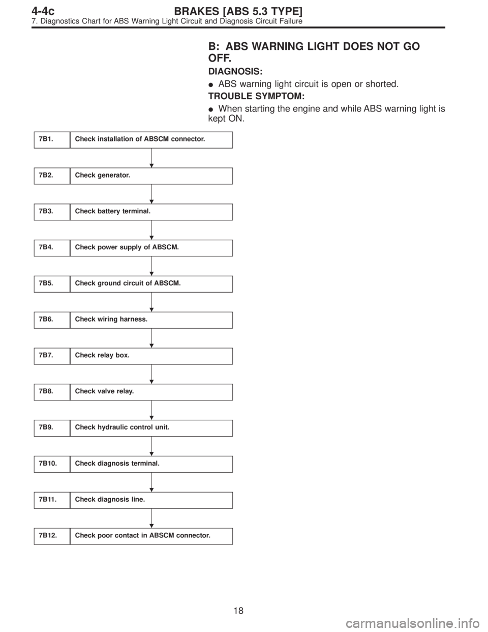
B: ABS WARNING LIGHT DOES NOT GO
OFF.
DIAGNOSIS:
�ABS warning light circuit is open or shorted.
TROUBLE SYMPTOM:
�When starting the engine and while ABS warning light is
kept ON.
7B1.Check installation of ABSCM connector.
7B2.Check generator.
7B3.Check battery terminal.
7B4.Check power supply of ABSCM.
7B5.Check ground circuit of ABSCM.
7B6.Check wiring harness.
7B7.Check relay box.
7B8.Check valve relay.
7B9.Check hydraulic control unit.
7B10.Check diagnosis terminal.
7B11.Check diagnosis line.
7B12.Check poor contact in ABSCM connector.
�
�
�
�
�
�
�
�
�
�
�
18
4-4cBRAKES [ABS 5.3 TYPE]
7. Diagnostics Chart for ABS Warning Light Circuit and Diagnosis Circuit Failure
Page 2624 of 3342
WIRING DIAGRAM:
B4M1034
7B1CHECK INSTALLATION OF ABSCM CON-
NECTOR.
Turn ignition switch to OFF.
: Is ABSCM connector inserted into ABSCM
until the clamp locks onto it?
: Go to step7B2.
: Insert ABSCM connector into ABSCM until the
clamp locks onto it.
19
4-4cBRAKES [ABS 5.3 TYPE]
7. Diagnostics Chart for ABS Warning Light Circuit and Diagnosis Circuit Failure
Page 2625 of 3342
B4M0430
7B2
CHECK GENERATOR.
1) Start the engine.
2) Idle the engine.
3) Measure voltage between generator and chassis
ground.
: Terminal
Generator B terminal (+)—Chassis ground
(�):
Is voltage 10—15 V?
: Go to step7B3.
: Repair generator.
7B3
CHECK BATTERY TERMINAL.
Turn ignition switch to OFF.
: Is there poor contact at battery terminal?
: Repair battery terminal.
: Go to step7B4.
B4M0796A
7B4
CHECK POWER SUPPLY OF ABSCM.
1) Disconnect connector from ABSCM.
2) Start engine.
3) Idle the engine.
4) Measure voltage between ABSCM connector and chas-
sis ground.
: Connector & terminal
(F49) No. 28 (+)—Chassis ground (�):
Is voltage 10—15 V?
: Go to step7B5.
: Repair ABSCM power supply circuit.
20
4-4cBRAKES [ABS 5.3 TYPE]
7. Diagnostics Chart for ABS Warning Light Circuit and Diagnosis Circuit Failure
.
: Do other warning lights turn on?
: Go to step7A2.
: Repair combination meter.
15
4-4cBRAKES")
 Turn ignition switch to OFF.
2) Remove combination meter.
3) Remove ABS warning light bulb from combination
meter.
: Is ABS warning light bulb OK?
: Go to step7A3.")
 Disconnect connector from relay box.
2) Turn ignition switch to ON.
3) Measure voltage between relay box and chassis
ground.
: Connector & terminal
To")

 Start the engine.
2) Idle the engine.
3) Measure voltage between generator and chassis
ground.
: Terminal
Generator B terminal (+)—Chassis ground
(�):
Is voltage 10�")