Page 2551 of 3342
 Turn ignition switch OFF.
2) Disconnect stroke sensor connectors.
3) Remove stroke sensor.
4) Measure the stroke sensor resistance against the rod
stroke.")
B4M0464A
3. CHECK STROKE SENSOR OPERATION.
1) Turn ignition switch OFF.
2) Disconnect stroke sensor connectors.
3) Remove stroke sensor.
4) Measure the stroke sensor resistance against the rod
stroke.
Terminal:
No. 3—No. 2
Stroke
Unit: mm (in)Specified
resistance
0—3.1±0.5 (0—0.122±0.020) 95—105Ω
3.1—5.5±0.5 (0.122—0.217±0.020) 190—210Ω
5.5—7.9±0.5 (0.217—0.311±0.020) 285—315Ω
7.9—10.3±0.5 (0.311—0.406±0.020) 380—420Ω
10.3—18±0.5 (0.406—0.709±0.020) 475—525Ω
NOTE:
Stroke = 0 when the stroke sensor rod is completely drawn
into the sensor unit.
B4M0465A
4. CHECK BODY SHORT OF STROKE SENSOR.
1) Turn ignition switch OFF.
2) Disconnect stroke sensor connectors.
3) Remove stroke sensor.
4) Measure resistance between stroke sensor terminal
and stroke sensor threads.
Terminal / Specified resistance:
No. 1—stroke sensor threads/ 1 MΩor more
No. 2—stroke sensor threads/ 1 MΩor more
No. 3—stroke sensor threads/ 1 MΩor more
B4M0466A
5. CHECK CONTACT POINT OF STOP LIGHT
SWITCH.
1) Turn ignition switch OFF.
2) Disconnect stroke sensor connectors.
3) Remove stroke sensor.
4) Measure resistance between stroke sensor terminals.
Terminal:
No. 2—No. 3
Stroke
Unit mm (in)Specified
resistance
0—2.2±1.0 (0—0.087±0.039) 1 MΩor more
2.2±1.0—18.0±0.5 (0.087±0.039—0.709±0.020) 1Ωor less
NOTE:
Stroke = 0 when the rod is completely drawn in.
75
4-4bBRAKES
8. Diagnostics Chart with Trouble Code
Page 2552 of 3342
 Turn ignition switch OFF.
2) Disconnect stroke sensor connectors.
3) Remove stroke sensor.
4) Measure resistance between stroke sensor terminal
an")
B4M0467A
6. CHECK BODY SHORT OF STOP LIGHT SWITCH.
1) Turn ignition switch OFF.
2) Disconnect stroke sensor connectors.
3) Remove stroke sensor.
4) Measure resistance between stroke sensor terminal
and stroke sensor threads.
Terminal / Specified resistance:
No. 2—stroke sensor threads/1MΩor more
No. 3—stroke sensor threads/1MΩor more
B4M0468A
7. CHECK POWER SUPPLY OF STOP LIGHT
SWITCH.
1) Turn ignition switch OFF.
2) Disconnect stroke sensor connector.
3) Measure voltage between stroke sensor connector and
body.
Connector & terminal / Specified voltage:
(B67) No. 3—body / 10—13 V
B4M0469A
8. CHECK INPUT VOLTAGE OF ABS/TCS CONTROL
MODULE.
1) Turn ignition switch OFF.
2) Install stroke sensor.
3) Connect stop light switch connector.
4) Disconnect ABS/TCS control module connector.
5) Measure voltage between ABS/TCS control module
connector and body.
Connector & terminal / Specified voltage:
(P7) No. 7—body / 10—13 V (With brake pedal
depressed)
(P7) No. 7—body/0V(Without brake pedal
depressed)
9. CHECK STOP LIGHT CIRCUIT.
1) Turn ignition switch OFF.
2) Install stroke sensor.
3) Connect stroke sensor connector.
4) Connect ABS/TCS control module connector.
5) Depress brake pedal and check that the stop light
comes on.
76
4-4bBRAKES
8. Diagnostics Chart with Trouble Code
Page 2553 of 3342
 Turn ignition switch OFF.
2) Install stroke sensor.
3) Connect stroke sensor connector.
4) Disconnect ABS/TCS control mo")
B4M0470A
10. CHECK HARNESS BETWEEN STROKE SENSOR
AND ABS/TCS CONTROL MODULE.
1) Turn ignition switch OFF.
2) Install stroke sensor.
3) Connect stroke sensor connector.
4) Disconnect ABS/TCS control module connector.
5) Measure resistance between ABS/TCS control module
connector terminals.
Connector & terminal / Specified resistance:
(P7) No. 4—No. 14 / 570—630Ω
(P7) No. 5—No. 14 / 95—105Ω
NOTE:
Do not depress brake pedal.
B4M0471A
11. CHECK BODY SHORT OF STROKE SENSOR
HARNESS.
1) Turn ignition switch OFF.
2) Connect stroke sensor connector.
3) Disconnect ABS/TCS control module connector.
4) Measure resistance between ABS/TCS control module
connector and body.
Connector & terminal / Specified resistance:
(P7) No. 4—body/1MΩor more
(P7) No. 5—body/1MΩor more
(P7) No. 14—body/1MΩor more
12. CHECK PUMP UNIT OPERATION.
1) Turn ignition switch OFF.
2) Connect stroke sensor connector.
3) Connect stop light switch connector.
4) Connect ABS/TCS control module connector.
5) Operate the TCS sequence control and check that the
front brake fluid pressure increases and decreases cor-
rectly.
77
4-4bBRAKES
8. Diagnostics Chart with Trouble Code
Page 2556 of 3342
 Turn ignition switch OFF.
2) Remove No. 18 fuse from fuse and joint box.
3) Disconnect ABS/TCS control module connectors.
4) Measure resistance between AB")
B4M0733A
3. CHECK GROUND SHORT OF HARNESS.
1) Turn ignition switch OFF.
2) Remove No. 18 fuse from fuse and joint box.
3) Disconnect ABS/TCS control module connectors.
4) Measure resistance between ABS/TCS control module
connector and body.
Connector & terminal / Specified resistance:
(P5) No. 1—body/1MΩor more
B4M0405A
4. CHECK GROUND CIRCUIT OF ABS/TCS CONTROL
MODULE.
1) Turn ignition switch OFF.
2) Disconnect connector from ABS/TCS control module.
3) Measure resistance between ABS/TCS control module
connector and body.
Connector & terminal / Specified resistance:
(P4) No. 6—body / 1Ωor less
(P5) No. 5—body / 1Ωor less
(P7) No. 15—body / 1Ωor less
5. CHECK GENERATOR FUNCTION.
1) When the ignition key is at OFF, check the charge warn-
ing light is off.
2) Turn the key ON and ensure the light comes on.
3) Keep the engine running at idle and ensure the light
goes off.
B4M0473A
B4M0395A
6. CHECK INPUT VOLTAGE OF ABS/TCS CONTROL
MODULE.
1) Turn ignition switch OFF.
2) Disconnect ABS/TCS control module connectors.
3) Turn ignition switch ON.
4) Measure voltage between ABS/TCS control module
connector and body.
Connector & terminal / Specified voltage:
(P7) No. 20—body/2Vorless (Engine OFF)
(P7) No. 20—body / 10—14 V (Engine idling)
(P5) No. 1—body / 10—13 V (Engine OFF)
80
4-4bBRAKES
8. Diagnostics Chart with Trouble Code
Page 2557 of 3342
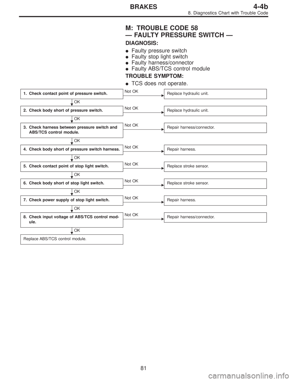
M: TROUBLE CODE 58
—FAULTY PRESSURE SWITCH—
DIAGNOSIS:
�Faulty pressure switch
�Faulty stop light switch
�Faulty harness/connector
�Faulty ABS/TCS control module
TROUBLE SYMPTOM:
�TCS does not operate.
1. Check contact point of pressure switch.
OK
�Not OK
Replace hydraulic unit.
2. Check body short of pressure switch.
OK
�Not OK
Replace hydraulic unit.
3. Check harness between pressure switch and
ABS/TCS control module.
OK
�Not OK
Repair harness/connector.
4. Check body short of pressure switch harness.
OK
�Not OK
Repair harness.
5. Check contact point of stop light switch.
OK
�Not OK
Replace stroke sensor.
6. Check body short of stop light switch.
OK
�Not OK
Replace stroke sensor.
7. Check power supply of stop light switch.
OK
�Not OK
Repair harness.
8. Check input voltage of ABS/TCS control mod-
ule.
OK
�Not OK
Repair harness/connector.
Replace ABS/TCS control module.
�
�
�
�
�
�
�
�
81
4-4bBRAKES
8. Diagnostics Chart with Trouble Code
Page 2559 of 3342
 Turn ignition switch OFF.
2) Disconnect hydraulic unit connector.
3) Measure resistance between hydraulic unit connector
and body.
Connector & termi")
B4M0735A
2. CHECK BODY SHORT OF PRESSURE SWITCH.
1) Turn ignition switch OFF.
2) Disconnect hydraulic unit connector.
3) Measure resistance between hydraulic unit connector
and body.
Connector & terminal / Specified resistance:
(F12) No. 1—body/1MΩor more
(F12) No. 2—body/1MΩor more
B4M0477A
3. CHECK HARNESS BETWEEN PRESSURE SWITCH
AND ABS/TCS CONTROL MODULE.
1) Turn ignition switch OFF.
2) Connect hydraulic unit connector.
3) Disconnect ABS/TCS control module connector.
4) Measure resistance between ABS/TCS control module
connector terminals.
Connector & terminal / Specified resistance:
(P7) No. 6—No.18/1MΩor more (With brake
pedal
depressed)
(P7) No. 6—No. 18 / 1Ωor less (Without brake
pedal depressed)
B4M0478A
4. CHECK BODY SHORT OF PRESSURE SWITCH
HARNESS.
1) Turn ignition switch OFF.
2) Disconnect ABS/TCS control module connector.
3) Measure resistance between ABS/TCS control module
connector and body.
Connector & terminal / Specified resistance:
(P7) No. 6—body/1MΩor more
(P7) No. 18—body/1MΩor more
B4M0466A
5. CHECK CONTACT POINT OF STOP LIGHT
SWITCH.
1) Turn ignition switch OFF.
2) Disconnect stop light switch connectors.
3) Remove stroke sensor.
4) Measure resistance between stroke sensor terminals.
83
4-4bBRAKES
8. Diagnostics Chart with Trouble Code
Page 2560 of 3342
Specified
resistance
0—2.2±1.0 (0—0.087±0.039) 1 MΩor more
2.2±1.0—18.0±0.5 (0.087±0.039—0.709±0.020) 1Ωor less
NOTE:
Stroke = 0 when the")
Terminal:
No. 2—No. 3
Stroke
Unit: mm (in)Specified
resistance
0—2.2±1.0 (0—0.087±0.039) 1 MΩor more
2.2±1.0—18.0±0.5 (0.087±0.039—0.709±0.020) 1Ωor less
NOTE:
Stroke = 0 when the rod is completely drawn in.
B4M0467A
6. CHECK BODY SHORT OF STOP LIGHT SWITCH.
1) Turn ignition switch OFF.
2) Disconnect stroke sensor connectors.
3) Remove stroke sensor.
4) Measure resistance between stroke sensor terminal
and stroke sensor threads.
Terminal / Specified resistance:
No. 2—stroke sensor threads/1MΩor more
No. 3—stroke sensor threads/1MΩor more
B4M0468A
7. CHECK POWER SUPPLY OF STOP LIGHT
SWITCH.
1) Turn ignition switch OFF.
2) Disconnect stroke sensor connector.
3) Measure voltage between stroke sensor connector and
body.
Connector & terminal / Specified voltage:
(B67) No. 3—body / 10—13 V
B4M0469A
8. CHECK INPUT VOLTAGE OF ABS/TCS CONTROL
MODULE.
1) Turn ignition switch OFF.
2) Install stroke sensor.
3) Connect stroke sensor connector.
4) Disconnect ABS/TCS control module connector.
5) Measure voltage between ABS/TCS control module
connector and body.
Connector & terminal / Specified voltage:
(P7) No. 7—body / 10—13 V (With brake pedal
depressed)
(P7) No. 7—body/0V(Without brake pedal
depressed)
84
4-4bBRAKES
8. Diagnostics Chart with Trouble Code
Page 2562 of 3342

If the system is in normal condition with the engine run at
idle speed (when the brake pedal is off), the LED of EC
(AEC signal) of FA2 will come on, the LED of")
2. FA MODE (ON/OFF DATA ARE DISPLAYED.)
If the system is in normal condition with the engine run at
idle speed (when the brake pedal is off), the LED of EC
(AEC signal) of FA2 will come on, the LED of EM (EAM
signal) blink and all other LED’s go out.
Function code
Measuring
itemsContents to be monitored Scroll Ref. to 4-4b
Code Abbreviation
FA 0OF OFF.SW LED 1 comes on with the OFF switch on.
Possible [T9H0] B1Stop light
switchLED 2 comes on with the switch on (with the brake
pedal down).
VRValve relay
signalLED 3 comes on with the valve relay off.
VMValve relay
monitorLED 4 comes on with the valve relay off.
MRMotor relay
signalLED 5 comes on with the motor on.
MS Motor sensor LED 6 comes on with the motor on.
FSFluid level
sensorLED 7 comes on with the sensor on (the fluid level
is lowered).
FA 1FI FR.IN valveLED 1 comes on when the FR.IN valve is operat-
ing.
Possible [T9I0] RO FR.OUT valveLED 2 comes on when the FR.OUT valve is operat-
ing.
FL FL.IN valve LED 3 comes on when the FL.IN valve is operating.
LO FL.OUT valveLED 4 comes on when the FL.OUT valve is operat-
ing.
T1 TCS1 valve LED 5 comes on when the TCS1 valve is operating.
RI RR.IN valveLED 6 comes on when the RR.IN valve is operat-
ing.
RO RR.OUT valveLED 7 comes on when the RR.OUT valve is operat-
ing.
RI RL.IN valve LED 8 comes on when the RL.IN valve is operating.
LO RL.OUT valveLED 9 comes on when the RL.OUT valve is operat-
ing.
T2 TCS2 valveLED 10 comes on when the TCS2 valve is operat-
ing.
FA 2AWABS warning
lightLED 1 comes on when the warning light is on.
Possible [T9J0] TWTCS warning
lightLED 2 comes on when the warning light is on.
TOTCS OFF
indicator lightLED 3 comes on when the indicator light is on.
TITCS operation
indicator lightLED 4 comes on when the indicator light is on.
EC AEC signalWith the engine run at idle speed, LED 6 (AEC)
comes on and LED 7 (AEB) goes out (They go on
and off depending on the behavior of a vehicle.) EB AEB signal
ET AET signal LED 8 comes on with the TCS control on.
EM EAM signalLED 9 comes on or blinks when the engine control
is enabled.
AT AAT signal LED 10 comes on when ABS control is on.
86
4-4bBRAKES
9. Select Monitor Function Mode