Page 2566 of 3342

—
�Compare speedometer with monitor indications.
�F04: RL wheel speed is indicated in mile per hour (mile/
h).
�F08: RL wheel speed i")
B4M0483
F: MODE F04 AND F08
—REAR LEFT WHEEL SPEED SIGNAL (RL)
—
�Compare speedometer with monitor indications.
�F04: RL wheel speed is indicated in mile per hour (mile/
h).
�F08: RL wheel speed is indicated in kilometer per hour
(km/h).
NOTE:
The monitor as shown, indicates that RL wheel speed is 50
mile/h.
B4M0484
G: MODE F09
—PEDAL STROKE SENSOR SIGNAL (PSS)
—
�Indicates the output step number of the pedal stroke
sensor.
LED No. Signal name Display
1 TCS OFF switch OF
2 Stop light switch B1
3 Valve relay signal VR
4 Valve relay monitor VM
5 Motor relay signal MR
6 Motor sensor MS
7 Brake fluid level sensor FS
8——
9——
10——
OF B1 VR VM MR
MS FS———
1
2345
678910
H: MODE FA0
—ON↔OFF SIGNAL—
Requirement for LED“ON”
LED No. 1 T.C.S OFF switch is turned ON.
LED No. 2 Stop light switch is turned ON. (With brake
pedal depressed.)
LED No. 3 Valve relay is turned OFF.
LED No. 4 Valve relay is turned OFF.
LED No. 5 Motor relay is turned ON.
LED No. 6 Motor is rotating.
LED No. 7 Brake fluid level sensor is turned ON. (Brake
fluid is insufficient.)
90
4-4bBRAKES
9. Select Monitor Function Mode
Page 2567 of 3342

LED No. Signal name Display
1Front right inlet solenoid
valveFI
2Front right outlet solenoid
valveRO
3Front left inlet solenoid
valveFI
4Front left outlet solenoid
valveLO
5Traction control solenoid
valve 1T1
6Rear right inlet solenoid
valveRI
7Rear right outlet solenoid
valveRO
8Rear left inlet solenoid
valveRI
9Rear left outlet solenoid
valveLO
10Traction control solenoid
valve 2T2
FI RO FI LO T1
RI RO RI LO T2
1
2345
678910
I: MODE FA1
—ON↔OFF SIGNAL—
Requirement for LED“ON”
LED No. 1 Front right inlet solenoid valve is in function.
LED No. 2 Front right outlet solenoid valve is in function.
LED No. 3 Front left inlet solenoid valve is in function.
LED No. 4 Front left outlet solenoid valve is in function.
LED No. 5 Traction control solenoid valve 1 is in func-
tion.
LED No. 6 Rear right inlet solenoid valve is in function.
LED No. 7 Rear right outlet solenoid valve is in function.
LED No. 8 Rear left inlet solenoid valve is in function.
LED No. 9 Rear left outlet solenoid valve is in function.
LED No. 10 Traction control solenoid valve 2 is in func-
tion.
LED No. Signal name Display
1 ABS warning light AW
2 TCS warning light TW
3 TCS OFF indicator light TO
4TCS operating indicator
lightTI
5——
6 AEC signal EC
7 AEB signal EB
8 AET signal ET
9 EAM signal EM
10 AAT signal AT
AW TW TO TI—
EC EB ET EM AT
1
2345
678910
J: MODE FA2
—ON↔OFF SIGNAL—
Requirement for LED“ON”
LED No. 1 ABS warning light is on.
LED No. 2 TCS warning light is on.
LED No. 3 TCS OFF indicator light is on.
LED No. 4 TCS operating indicator light is on.
LED No. 6 Engine is running at idle. (LED comes on or
goes off depending on vehicle movement.)
LED No. 7 Engine is running at idle. (LED comes on or
goes off depending on vehicle movement.)
LED No. 8 TCS control operates.
LED No. 9 Engine control is permitted.
LED No. 10 ABS control operates.
NOTE:
If the system is normal when idling the engine without
depressing brake pedal, LED No. 6 comes on, LED No. 9
blinks and all other LED’s are off.
91
4-4bBRAKES
9. Select Monitor Function Mode
Page 2571 of 3342
CodeDisplay screen
(FB0)Diagnostic items (select monitor FB1) Display screen (FB1)Ref. to
4-4b
Abnormal stroke sen-
sor and stop light
switch54 PSS & BLSOpen/short")
Diagnostic items
(select monitor FB0)CodeDisplay screen
(FB0)Diagnostic items (select monitor FB1) Display screen (FB1)Ref. to
4-4b
Abnormal stroke sen-
sor and stop light
switch54 PSS & BLSOpen/short circuits of stroke sensor B.SW HARD [T10Y1]
Comparison of stroke sensor and acceleration B.SW SOFT(G) [T10Y2]
Comparison of stroke sensor and stop light switch B.SW SOFT(B) [T10Y3]
Comparison of stroke sensor and pump B.SW SOFT(P) [T10Y4]
Open circuit of stop light switch B.SW SOFT(O) [T10Y5]
Abnormal fluid level
sensor line57 FLUID LEVEL SS Abnormal fluid level sensor line FLUID LEVEL SS [T10Z0]
Abnormal pressure
switch58 PRESSURE SW Abnormal pressure switch PRESSURE SW [T10AA0]
Abnormal TCS1 valve 61 TCS1 VALVE Abnormal TCS1 valve TCS1 VALVE [T10AB0]
Abnormal TCS2 valve 62 TCS2 VALVE Abnormal TCS2 valve TCS2 VALVE [T10AC0]
1. IF THE SELECT MONITOR IS USED FOR
TROUBLESHOOTING, IT IS ADVISED TO FOLLOW
THE PROCEDURE BELOW
1) Activate function FB0 to read the most recent trouble
code and record it.
2) Activate function FB1 to read all trouble codes and
record them.
(If troubles occur in the wheel speed sensor, stop & brake
switch, valve relay or motor system, detailed data on
troubles are displayed by the FB1 function, allowing you to
easily locate points where need repair.)
3) Perform troubleshooting mainly in the FB1 mode.
95
4-4bBRAKES
10. Diagnostic Chart with Select Monitor
Page 2595 of 3342

B4M0526
Y: TROUBLE CODE 54
1. B.SW HARD
—Break and short circuit at stroke sensor or its
wiring—
DIAGNOSIS:
�Faulty stroke sensor
�Faulty harness/connector
�Faulty stop light switch
�Faulty ABS/TCS control module
TROUBLE SYMPTOM:
�ABS and TCS do not operate.
NOTE:
Operate the function F09 in select monitor TCS mode, and
read the sensor output step.
If system is normal, the output reading is 1 when brake
pedal is not depressed, and it changes from 2 to 3, 4 and
5 in accordance with the brake pedal depressing. If so, skip
check steps 1 through 5.
1. Check resistance of stroke sensor.
OK
�Not OK
Replace stroke sensor.
2. Check stroke sensor operation.
OK
�Not OK
Replace stroke sensor.
3. Check body short of stroke sensor.
OK
�Not OK
Replace stroke sensor.
4. Check harness between stroke sensor and
ABS/TCS control module.
OK
�Not OK
Repair harness/connector.
5. Check body short of stroke sensor harness.
OK
�Not OK
Repair harness.
Replace ABS/TCS control module.
�
�
�
�
�
11 9
4-4bBRAKES
10. Diagnostic Chart with Select Monitor
Page 2596 of 3342
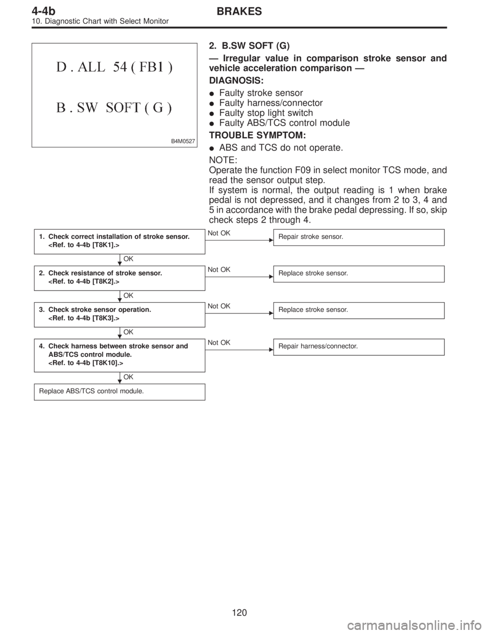
B4M0527
2. B.SW SOFT (G)
—Irregular value in comparison stroke sensor and
vehicle acceleration comparison—
DIAGNOSIS:
�Faulty stroke sensor
�Faulty harness/connector
�Faulty stop light switch
�Faulty ABS/TCS control module
TROUBLE SYMPTOM:
�ABS and TCS do not operate.
NOTE:
Operate the function F09 in select monitor TCS mode, and
read the sensor output step.
If system is normal, the output reading is 1 when brake
pedal is not depressed, and it changes from 2 to 3, 4 and
5 in accordance with the brake pedal depressing. If so, skip
check steps 2 through 4.
1. Check correct installation of stroke sensor.
OK
�Not OK
Repair stroke sensor.
2. Check resistance of stroke sensor.
OK
�Not OK
Replace stroke sensor.
3. Check stroke sensor operation.
OK
�Not OK
Replace stroke sensor.
4. Check harness between stroke sensor and
ABS/TCS control module.
OK
�Not OK
Repair harness/connector.
Replace ABS/TCS control module.
�
�
�
�
120
4-4bBRAKES
10. Diagnostic Chart with Select Monitor
Page 2597 of 3342

—Irregular value in stroke sensor and brake light
switch comparison—
DIAGNOSIS:
�Faulty stroke sensor
�Faulty stop light switch
�Faulty harness/connector
�Faulty ABS/TCS c")
B4M0528
3. B.SW SOFT (B)
—Irregular value in stroke sensor and brake light
switch comparison—
DIAGNOSIS:
�Faulty stroke sensor
�Faulty stop light switch
�Faulty harness/connector
�Faulty ABS/TCS control module
TROUBLE SYMPTOM:
�ABS and TCS do not operate.
NOTE:
Operate the function F09 in select monitor TCS mode, and
read the sensor output step.
If system is normal, the output reading is 1 when brake
pedal is not depressed, and it changes from 2 to 3, 4 and
5 in accordance with the brake pedal depressing. If so, skip
check steps 1 and 2 through 7.
Then, operate the function FA0 and check the stop and
brake switches by B1 LED ON/OFF. If system is normal,
LED comes on when depressing brake pedal, and goes off
when not depressing. If so, skip check steps 3 through 6.
1. Check resistance of stroke sensor.
OK
�Not OK
Replace stroke sensor.
2. Check stroke sensor operation.
OK
�Not OK
Replace stroke sensor.
3. Check contact point of stop light switch.
OK
�Not OK
Replace stroke sensor.
4. Check body short of stop light switch.
OK
�Not OK
Replace stroke sensor.
5. Check power supply of stop light switch.
OK
�Not OK
Repair harness/connector.
6. Check input voltage of ABS/TCS control mod-
ule.
OK
�Not OK
Repair harness/connector.
7. Check harness between stroke sensor and
ABS/TCS control module.
OK
�Not OK
Repair harness/connector.
Replace ABS/TCS control module.
�
�
�
�
�
�
�
121
4-4bBRAKES
10. Diagnostic Chart with Select Monitor
Page 2598 of 3342

—Comparison between stroke sensor and pump
output—
DIAGNOSIS:
�Faulty stroke sensor
�Faulty harness/connector
�Faulty pump unit in hydraulic unit
�Faulty stop light switch")
B4M0529
4. B.SW SOFT (P)
—Comparison between stroke sensor and pump
output—
DIAGNOSIS:
�Faulty stroke sensor
�Faulty harness/connector
�Faulty pump unit in hydraulic unit
�Faulty stop light switch
�Faulty ABS/TCS control module
NOTE:
Operate the function F09 in select monitor TCS mode, and
read the sensor output step.
If system is normal, the output reading is 1 when brake
pedal is not depressed, and it changes from 2 to 3, 4 and
5 in accordance with the brake pedal depressing. If so, skip
check steps 2 through 4.
1. Check correct installation of stroke sensor.
OK
�Not OK
Repair stroke sensor.
2. Check resistance of stroke sensor.
OK
�Not OK
Replace stroke sensor.
3. Check stroke sensor operation.
OK
�Not OK
Replace stroke sensor.
4. Check harness between stroke sensor and
ABS/TCS control module.
OK
�Not OK
Repair harness/connector.
5. Check pump unit operation.
OK
�Not OK
Replace hydraulic unit.
Replace ABS/TCS control module.
�
�
�
�
�
122
4-4bBRAKES
10. Diagnostic Chart with Select Monitor
Page 2599 of 3342
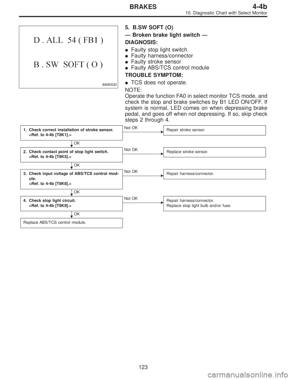
B4M0530
5. B.SW SOFT (O)
—Broken brake light switch—
DIAGNOSIS:
�Faulty stop light switch
�Faulty harness/connector
�Faulty stroke sensor
�Faulty ABS/TCS control module
TROUBLE SYMPTOM:
�TCS does not operate.
NOTE:
Operate the function FA0 in select monitor TCS mode, and
check the stop and brake switches by B1 LED ON/OFF. If
system is normal, LED comes on when depressing brake
pedal, and goes off when not depressing. If so, skip check
steps 2 through 4.
1. Check correct installation of stroke sensor.
OK
�Not OK
Repair stroke sensor.
2. Check contact point of stop light switch.
OK
�Not OK
Replace stroke sensor.
3. Check input voltage of ABS/TCS control mod-
ule.
OK
�Not OK
Repair harness/connector.
4. Check stop light circuit.
OK
�Not OK
Repair harness/connector.
Replace stop light bulb and/or fuse.
Replace ABS/TCS control module.
�
�
�
�
123
4-4bBRAKES
10. Diagnostic Chart with Select Monitor