Page 2507 of 3342
B4M0720A
1. CHECK TCS OFF SWITCH.
1) Turn ignition switch OFF.
2) Disconnect connector from TCS OFF switch.
3) Measure resistance between TCS OFF switch termi-
nals.
Connector & terminal / Specified resistance:
(i9) No. 5—No.3/1Ωor less
(When the switch is pressed,
turns ON.)
/1MΩor less
(When the switch is released,
turns OFF.)
B4M0401A
2. CHECK HARNESS CONNECTOR BETWEEN ABS/
TCS CONTROL MODULE AND TCS OFF SWITCH.
1) Turn ignition switch OFF.
2) Disconnect connector to TCS OFF switch.
3) Disconnect connector from ABS/TCS control module.
4) Measure resistance between ABS/TCS control module
connector terminals.
Connector & terminal / Specified resistance:
(P7) No. 16—body / 1Ωor less (When the switch
is pressed, turns ON.)
/1MΩor more (When the
switch is released, turns OFF.)
31
4-4bBRAKES
7. Diagnostics Chart for Warning Light Circuit Failure
Page 2508 of 3342
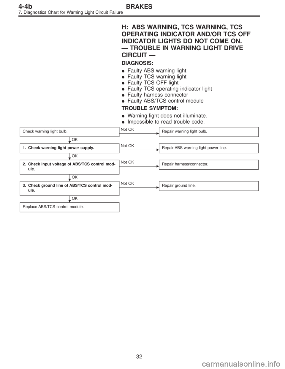
H: ABS WARNING, TCS WARNING, TCS
OPERATING INDICATOR AND/OR TCS OFF
INDICATOR LIGHTS DO NOT COME ON.
—TROUBLE IN WARNING LIGHT DRIVE
CIRCUIT—
DIAGNOSIS:
�Faulty ABS warning light
�Faulty TCS warning light
�Faulty TCS OFF light
�Faulty TCS operating indicator light
�Faulty harness connector
�Faulty ABS/TCS control module
TROUBLE SYMPTOM:
�Warning light does not illuminate.
�Impossible to read trouble code.
Check warning light bulb.
OK
�Not OK
Repair warning light bulb.
1. Check warning light power supply.
OK
�Not OK
Repair ABS warning light power line.
2. Check input voltage of ABS/TCS control mod-
ule.
OK
�Not OK
Repair harness/connector.
3. Check ground line of ABS/TCS control mod-
ule.
OK
�Not OK
Repair ground line.
Replace ABS/TCS control module.
�
�
�
�
32
4-4bBRAKES
7. Diagnostics Chart for Warning Light Circuit Failure
Page 2509 of 3342
B4M0402
B4M0403A
1. CHECK WARNING LIGHT POWER SUPPLY.
1) Turn ignition switch OFF.
2) Disconnect combination meter.
3) Turn ignition switch ON.
4) Measure voltage between combination meter connector
and body.
Connector & terminal / Specified voltage:
(i14) No. 11—body / 10—13 V
33
4-4bBRAKES
7. Diagnostics Chart for Warning Light Circuit Failure
Page 2510 of 3342
B4M0404A
2. CHECK INPUT VOLTAGE OF ABS/TCS CONTROL
MODULE.
1) Turn ignition switch OFF and connect combination
meter connector.
2) Disconnect all connectors from ABS/TCS control mod-
ule.
3) Remove ABS/TCS valve relay.
4) Turn ignition switch ON.
5) Measure voltage between ABS/TCS control module and
body.
Connector & terminal / Specified voltage:
ABS warning:
(P6) No. 2—body / 10—13 V
TCS warning:
(P6) No. 3—body / 10—13 V
TCS operation:
(P6) No. 11—body / 10—13 V
TCS OFF:
(P6) No. 10—body / 10—13 V
B4M0405A
3. CHECK GROUND LINE OF ABS/TCS CONTROL
MODULE.
Measure resistance between ABS/TCS control module and
body.
Connector & terminal / Specified resistance:
(P4) No. 6—body / 1Ωor less
(P5) No. 5—body / 1Ωor less
(P7) No. 15—body / 1Ωor less
34
4-4bBRAKES
7. Diagnostics Chart for Warning Light Circuit Failure
Page 2511 of 3342

8. Diagnostics Chart with Trouble Code
A: LIST OF TROUBLE CODE
Trouble code Contents of diagnosis Ref. to 4-4b
11Start code
�Trouble code is shown after start code.
�Only start code is shown in normal condition.—
21
Faulty ABS sensor
(Open circuit or short circuit)Front right wheel speed sensor
[T8B0] 23 Front left wheel speed sensor
25 Rear right wheel speed sensor
27 Rear left wheel speed sensor
22
Faulty ABS sensor
(Faulty ABS sensor signal)Front right wheel speed sensor
[T8C0] 24 Front left wheel speed sensor
26 Rear right wheel speed sensor
28 Rear left wheel speed sensor
31
Faulty solenoid valve circuit(s) in hydraulic
unitFront right inlet valve [T8D0]
32 Front right outlet valve [T8E0]
33 Front left inlet valve [T8D0]
34 Front left outlet valve [T8E0]
35 Rear right inlet valve [T8D0]
36 Rear right outlet valve [T8E0]
37 Rear left inlet valve [T8D0]
38 Rear left outlet valve [T8E0]
41 Faulty ABS/TCS control module [T8F0]
42 Source voltage is high.[T8G0]
43 Faulty engine control module communication cables [T8H0]
51 Faulty valve relay[T8I0]
52 Faulty motor, motor sensor and/or motor relay [T8J0]
54 Faulty stroke sensor and/or stop light switch [T8K0]
57 Faulty fluid level sensor[T8L0]
58 Faulty pressure switch[T8M0]
61
Faulty solenoid valve circuit(s) in hydraulic
unitTCS 1 valve [T8D0]
62 TCS 2 valve [T8D0]
35
4-4bBRAKES
8. Diagnostics Chart with Trouble Code
Page 2546 of 3342
 Turn ignition switch OFF.
2) Connect motor sensor connector.
3) Disconnect ABS/TCS control module.
4) Measure resistance b")
B4M0456A
8. CHECK HARNESS BETWEEN ABS/TCS CONTROL
MODULE AND MOTOR SENSOR.
1) Turn ignition switch OFF.
2) Connect motor sensor connector.
3) Disconnect ABS/TCS control module.
4) Measure resistance between ABS/TCS control module
connector terminals.
Connector & terminal / Specified resistance:
(P7) No. 3—No. 13 / 72—98Ω
B4M0457A
9. CHECK BODY SHORT OF MOTOR SENSOR
HARNESS.
1) Turn ignition switch OFF.
2) Connect motor sensor connector.
3) Disconnect ABS/TCS control module.
4) Measure resistance between ABS/TCS control module
and body.
Connector & terminal / Specified resistance:
(P7) No. 3—body/1MΩor more
(P7) No. 13—body/1MΩor more
B4M0458A
10. CHECK CONTACT POINT OF MOTOR RELAY.
1) Connect motor relay.
2) Connect ABS/TCS control module.
3) Operate the TCS sequence check.
[W20F0].>
4) Measure voltage between motor relay connector and
body.
Connector & terminal / Specified voltage:
(F10) No. 4—body / 10—14 V (While TCS oper-
ating indicator light is ON.)
B4M0459A
11. CHECK HARNESS BETWEEN MOTOR AND
MOTOR RELAY.
1) Turn ignition switch OFF.
2) Disconnect motor relay.
3) Disconnect motor connector.
4) Measure resistance between motor relay connector and
motor connector.
Connector & terminal / Specified resistance:
(F13) No. 2—(F10) No.4/1Ωor less
B4M0460A
12. CHECK BODY SHORT OF MOTOR HARNESS.
1) Turn ignition switch OFF.
2) Disconnect motor relay.
3) Disconnect motor connector.
4) Measure resistance between motor connector and
body.
Connector & terminal / Specified resistance:
(F13) No. 2—body/1MΩor more
70
4-4bBRAKES
8. Diagnostics Chart with Trouble Code
Page 2548 of 3342
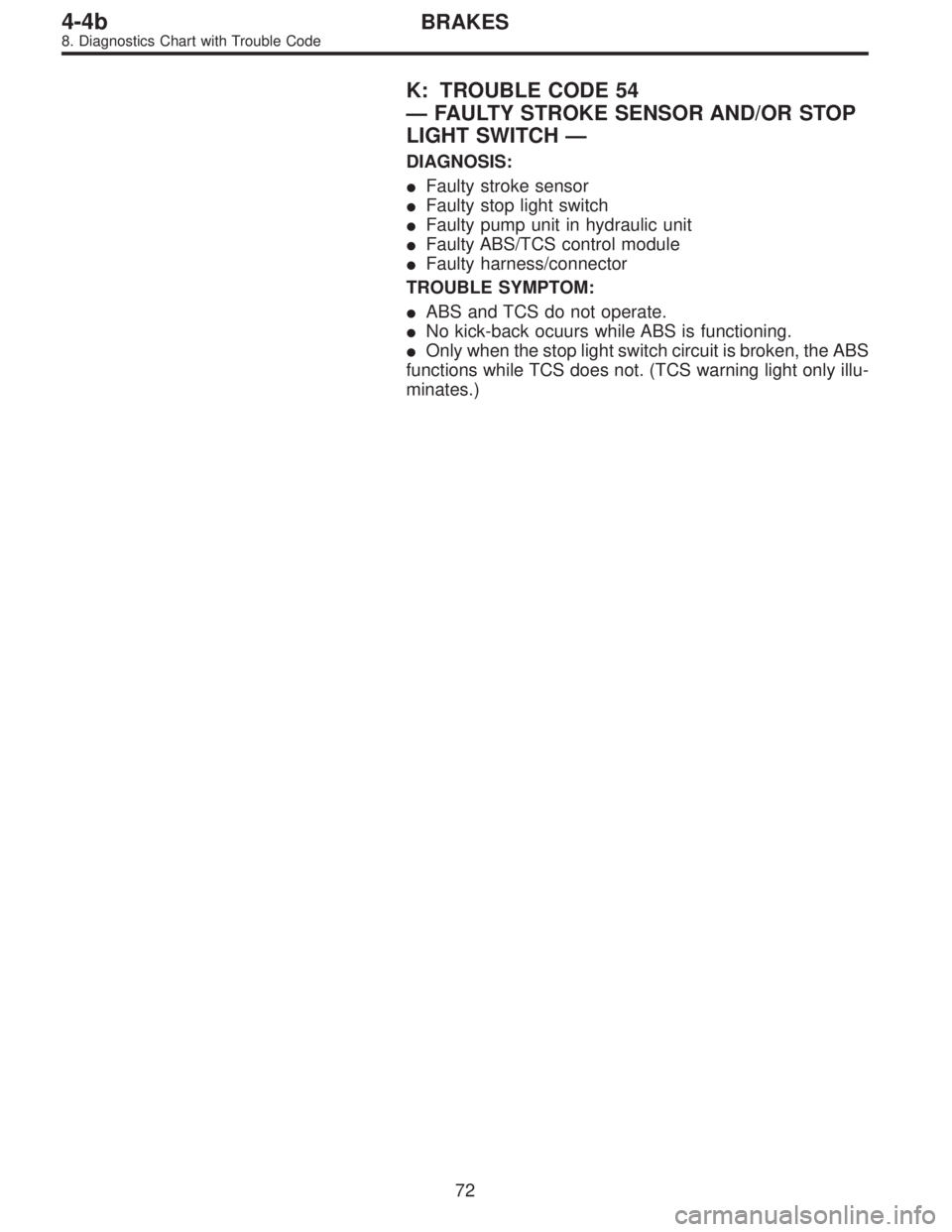
K: TROUBLE CODE 54
—FAULTY STROKE SENSOR AND/OR STOP
LIGHT SWITCH—
DIAGNOSIS:
�Faulty stroke sensor
�Faulty stop light switch
�Faulty pump unit in hydraulic unit
�Faulty ABS/TCS control module
�Faulty harness/connector
TROUBLE SYMPTOM:
�ABS and TCS do not operate.
�No kick-back ocuurs while ABS is functioning.
�Only when the stop light switch circuit is broken, the ABS
functions while TCS does not. (TCS warning light only illu-
minates.)
72
4-4bBRAKES
8. Diagnostics Chart with Trouble Code
Page 2549 of 3342

1. Check correct installation of stroke sensor.
OK
�Not OK
Repair stroke sensor.
2. Check resistance of stroke sensor.
OK
�Not OK
Replace stroke sensor.
3. Check stroke sensor operation.
OK
�Not OK
Replace stroke sensor.
4. Check body short of stroke sensor.
OK
�Not OK
Replace stroke sensor.
5. Check contact point of stop light switch.
OK
�Not OK
Replace stroke sensor.
6. Check body short of stop light switch.
OK
�Not OK
Replace stroke sensor.
7. Check power supply of stop light switch.
OK
�Not OK
Repair harness/connector.
8. Check input voltage of ABS/TCS control mod-
ule.
OK
�Not OK
Repair harness/connector.
9. Check stop light circuit.
OK
�Not OK
Repair harness/connector.
Replace stop light bulb and/or fuse.
10. Check harness between stroke sensor and
ABS/TCS control module.
OK
�Not OK
Repair harness/connector.
11. Check body short of stroke sensor harness.
OK
�Not OK
Repair harness.
12. Check pump unit operation.
OK
�Not OK
Replace hydraulic unit.
Replace ABS/TCS control module.
�
�
�
�
�
�
�
�
�
�
�
�
73
4-4bBRAKES
8. Diagnostics Chart with Trouble Code
 Turn ignition switch OFF.
2) Disconnect connector from TCS OFF switch.
3) Measure resistance between TCS OFF switch termi-
nals.
Connector & terminal / Specified r")
 Turn ignition switch OFF.
2) Disconnect combination meter.
3) Turn ignition switch ON.
4) Measure voltage between combination meter connector
a")
 Turn ignition switch OFF and connect combination
meter connector.
2) Disconnect all connectors from ABS/TCS control mod-
ule.
3) Remove AB")