Page 2879 of 3342
B: ELECTRICAL INSPECTION
1. WARNING LIGHT ILLUMINATION PATTERN
B4M0781A
1) When the ABS warning light does not illuminate in
accordance with this illumination pattern, there must be an
electrical malfunction.
2) When the ABS warning light remains constantly OFF,
repair the ABS warning light circuit or diagnosis circuit.
NOTE:
Even though the ABS warning light does not go out 1.5
seconds after it illuminates, the ABS system operates nor-
mally when the warning light goes out while driving at
approximately 12 km/h (7 MPH). However, the Anti-lock
brakes do not work while the ABS warning light is illumi-
nated.
3
4-4dBRAKES [ABS 5.3i TYPE]
2. Pre-inspection
Page 2880 of 3342
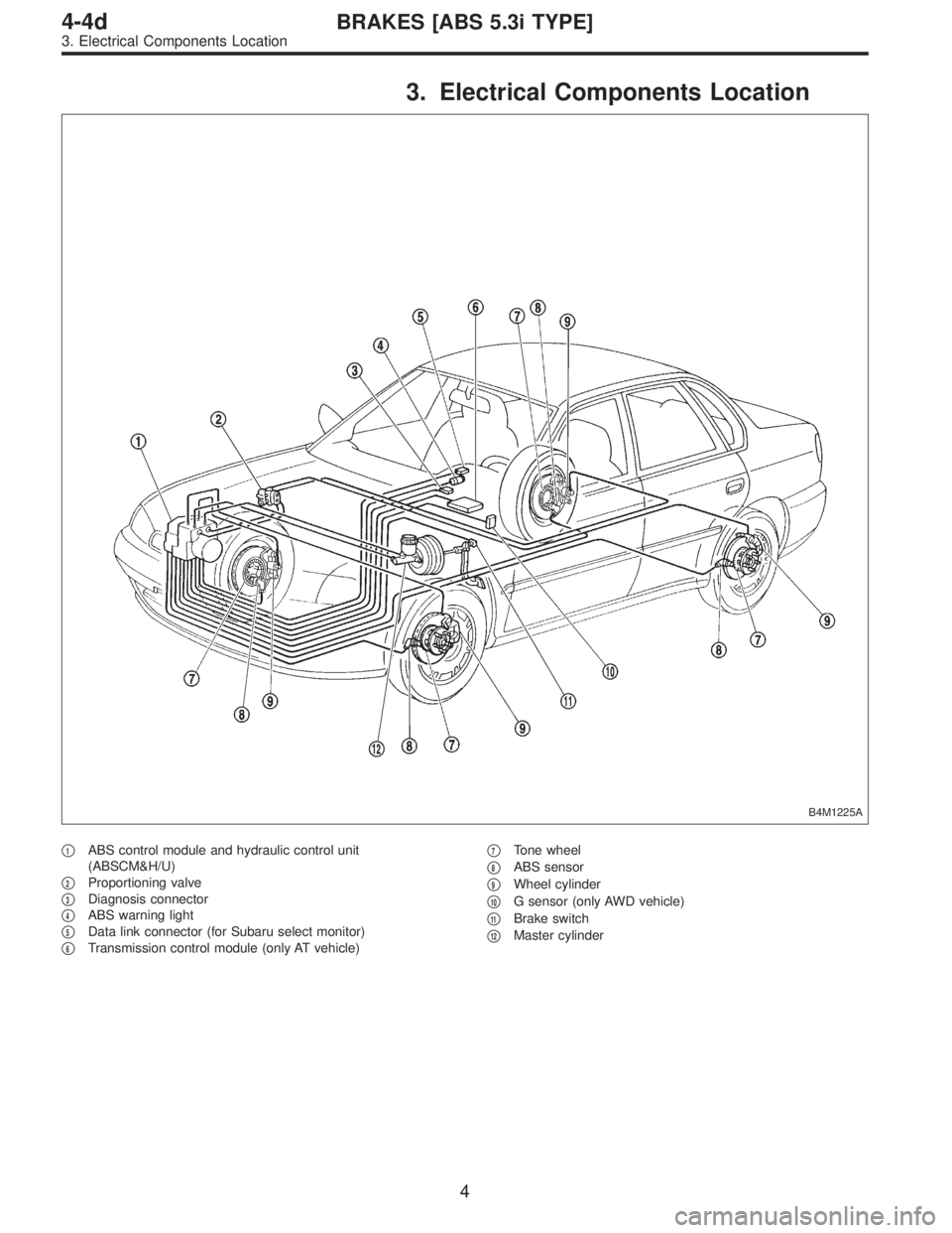
3. Electrical Components Location
B4M1225A
�1ABS control module and hydraulic control unit
(ABSCM&H/U)
�
2Proportioning valve
�
3Diagnosis connector
�
4ABS warning light
�
5Data link connector (for Subaru select monitor)
�
6Transmission control module (only AT vehicle)�
7Tone wheel
�
8ABS sensor
�
9Wheel cylinder
�
10G sensor (only AWD vehicle)
�
11Brake switch
�
12Master cylinder
4
4-4dBRAKES [ABS 5.3i TYPE]
3. Electrical Components Location
Page 2882 of 3342
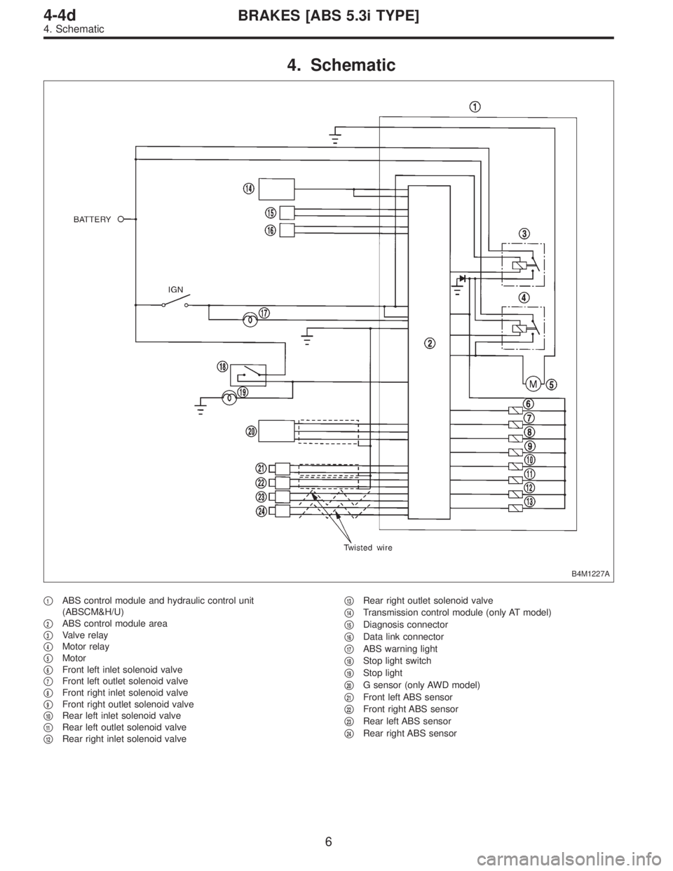
4. Schematic
B4M1227A
�1ABS control module and hydraulic control unit
(ABSCM&H/U)
�
2ABS control module area
�
3Valve relay
�
4Motor relay
�
5Motor
�
6Front left inlet solenoid valve
�
7Front left outlet solenoid valve
�
8Front right inlet solenoid valve
�
9Front right outlet solenoid valve
�
10Rear left inlet solenoid valve
�
11Rear left outlet solenoid valve
�
12Rear right inlet solenoid valve�
13Rear right outlet solenoid valve
�
14Transmission control module (only AT model)
�
15Diagnosis connector
�
16Data link connector
�
17ABS warning light
�
18Stop light switch
�
19Stop light
�
20G sensor (only AWD model)
�
21Front left ABS sensor
�
22Front right ABS sensor
�
23Rear left ABS sensor
�
24Rear right ABS sensor
6
4-4dBRAKES [ABS 5.3i TYPE]
4. Schematic
Page 2883 of 3342
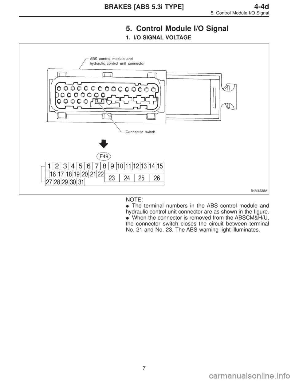
5. Control Module I/O Signal
1. I/O SIGNAL VOLTAGE
B4M1228A
NOTE:
�The terminal numbers in the ABS control module and
hydraulic control unit connector are as shown in the figure.
�When the connector is removed from the ABSCM&H/U,
the connector switch closes the circuit between terminal
No. 21 and No. 23. The ABS warning light illuminates.
7
4-4dBRAKES [ABS 5.3i TYPE]
5. Control Module I/O Signal
Page 2884 of 3342
—(�)Input/Output signal
Measured value and measuring conditions
ABS
sensor*2
(Wheel
speed
sensor)Front left wheel 9—10
0.12 — 1 V
(When it is 20 Hz.) Front right wheel 11")
ContentsTerminal No.
(+)—(�)Input/Output signal
Measured value and measuring conditions
ABS
sensor*2
(Wheel
speed
sensor)Front left wheel 9—10
0.12 — 1 V
(When it is 20 Hz.) Front right wheel 11—12
Rear left wheel 7—8
Rear right wheel 14—15
Valve relay power supply 24—23 10 — 15 V when ignition switch is ON.
Motor relay power supply 25—23 10 — 15 V when ignition switch is ON.
G sensor*2
(AWD
model only)power supply 30—28 4.75 — 5.25 V
ground 28 —
output 6—28 2.3±0.2 V when vehicle is in horizontal position.
Stop light switch*1 2—23Less than 1.5 V when the stop light is OFF and, 10 — 15 V
when the stop light is ON.
ABS warning light*2 21—23Less than 1.5 V during 1.5 seconds when ignition switch is
ON, and 10 — 15 V after 1.5 seconds.
AT ABS signal*2
(AT model only)31—23Less than 1.5 V when the ABS control does not operate still
and more than 5.5 V when ABS operates.
ABS operation signal monitor*2 3—23Less than 1.5 V when the ABS control does not operate still
and more than 5.5 V when ABS operates.
Select
monitor*2Data is received. 20—23 Less than 1.5 V when no data is received.
Data is sent. 5—23 4.75 — 5.25 V when no data is sent.
ABS
diagnosis
connector*2Terminal No. 3 29—23 10 — 15 V when ignition switch is ON.
Terminal No. 6 4—23 10 — 15 V when ignition switch is ON.
Power supply*1 1—23 10 — 15 V when ignition switch is ON.
Grounding line 23 —
Grounding line 26 —
*1: Measure the I/O signal voltage after removing the connector from the ABSCM&H/U terminal.
*2: Measure the I/O signal voltage at connector (F2) or (F1).
8
4-4dBRAKES [ABS 5.3i TYPE]
5. Control Module I/O Signal
Page 2887 of 3342

�When ABS warning light illuminates, read and record
trouble code indicated by ABS warning light.
B: CHECK LIST FOR INTERVIEW
Check the following items about the vehicle’s state.
1. THE STATE OF THE ABS WARNING LIGHT
ABS warning light
comes on.�Always
�Sometimes
�Only once
�Does not come on
�When /how long does it come on?:
Ignition key position�LOCK
�ACC
�ON (before starting engine)
�START
�On after starting (Engine is running)
�On after starting (Engine is stop)
Timing�Immediately after ignition is ON.
�Immediately after ignition starts.
�When advancing km/h to km/h
MPH to MPH
�While traveling at a constant speed km/h MPH
�When decelerating km/h to km/h
MPH to MPH
�When turning to right Steering angle : deg
Steering time : sec
�When turning to left Steering angle : deg
Steering time : sec
�When moving other electrical parts
�Parts name :
�Operating condition :
2. SYMPTOMS
ABS operating
condition�Performs no work.
�Operates only when abruptly applying brakes. Vehicle speed : km/h
MPH
�How to step on brake pedal :
a) Operating time :sec
b) Operating noise :�Produce /�Does not produce
�What kind of noise?�Knock
�Gong gong
�Bong
�Buzz
�Gong gong buzz
�Others :
c) Reaction force of brake pedal
�Stick
�Press down once with a clunk
�Press and released
�Others :
11
4-4dBRAKES [ABS 5.3i TYPE]
6. Diagnostics Chart for On-board Diagnosis System
Page 2890 of 3342

for at least one minute.
B4M0082D
D: TROUBL")
C: INSPECTION MODE
Reproduce the condition under which the problem has
occurred as much as possible.
Drive the vehicle at a speed more than 40 km/h (25 MPH)
for at least one minute.
B4M0082D
D: TROUBLE CODES
When on-board diagnosis of the ABS control module
detects a problem, the information (up to a maximum of
three) will be stored in the EEP ROM as a trouble code.
When there are more than three, the most recent three will
be stored. (Stored codes will stay in memory until they are
cleared.)
1. CALLING UP A TROUBLE CODE
1) Take out diagnosis connector from side of driver’s seat
heater unit.
2) Turn ignition switch OFF.
3) Connect diagnosis connector terminal 6 to diagnosis
terminal.
4) Turn ignition switch ON.
5) ABS warning light is set in the diagnostic mode and
blinks to identify trouble code.
6) After the start code (11) is shown, the trouble codes will
be shown in order of the last information first.
These repeat for a maximum of 5 minutes.
NOTE:
When there are no trouble codes in memory, only the start
code (11) is shown.
B4M0232A
14
4-4dBRAKES [ABS 5.3i TYPE]
6. Diagnostics Chart for On-board Diagnosis System
Page 2892 of 3342
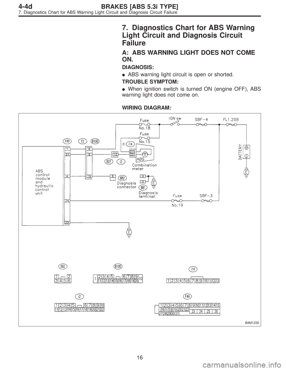
7. Diagnostics Chart for ABS Warning
Light Circuit and Diagnosis Circuit
Failure
A: ABS WARNING LIGHT DOES NOT COME
ON.
DIAGNOSIS:
�ABS warning light circuit is open or shorted.
TROUBLE SYMPTOM:
�When ignition switch is turned ON (engine OFF), ABS
warning light does not come on.
WIRING DIAGRAM:
B4M1230
16
4-4dBRAKES [ABS 5.3i TYPE]
7. Diagnostics Chart for ABS Warning Light Circuit and Diagnosis Circuit Failure
 When the ABS warning light does not illuminate in
accordance with this illumination pattern, there must be an
electrical malf")