Page 2893 of 3342
7A1CHECK IF OTHER WARNING LIGHTS
TURN ON.
Turn ignition switch to ON (engine OFF).
: Do other warning lights turn on?
: Go to step7A2.
: Repair combination meter.
7A2
CHECK ABS WARNING LIGHT BULB.
1) Turn ignition switch to OFF.
2) Remove combination meter.
3) Remove ABS warning light bulb from combination
meter.
: Is ABS warning light bulb OK?
: Go to step7A3.
: Replace ABS warning light bulb.
B4M1273A
7A3CHECK BATTERY SHORT OF ABS
WARNING LIGHT HARNESS.
1) Disconnect connector (B100) from connector (F2).
2) Measure voltage between connector (B100) and chas-
sis ground.
Connector & terminal
(B100) No. 9 (+) — Chassis ground (�):
: Is the voltage less than 3 V?
: Go to step7A4.
: Repair warning light harness.
17
4-4dBRAKES [ABS 5.3i TYPE]
7. Diagnostics Chart for ABS Warning Light Circuit and Diagnosis Circuit Failure
Page 2894 of 3342
B4M1273A
7A4CHECK BATTERY SHORT OF ABS
WARNING LIGHT HARNESS.
1) Turn ignition switch to ON.
2) Measure voltage between connector (B100) and chas-
sis ground.
Connector & terminal
(B100) No. 9 (+)—Chassis ground (�):
: Is voltage less than 3 V?
: Go to step7A5.
: Repair warning light harness.
B4M1273A
7A5
CHECK WIRING HARNESS.
1) Turn ignition switch to OFF.
2) Install ABS warning light bulb from combination meter.
3) Install combination meter.
4) Turn ignition switch to ON.
5) Measure voltage between connector (B100) and chas-
sis ground.
Connector & terminal
(B100) No. 9 (+)—Chassis ground (�):
: Is voltage between 10 V and 15 V?
: Go to step7A6.
: Repair wiring harness.
18
4-4dBRAKES [ABS 5.3i TYPE]
7. Diagnostics Chart for ABS Warning Light Circuit and Diagnosis Circuit Failure
Page 2895 of 3342
B4M1274A
7A6CHECK BATTERY SHORT OF ABS
WARNING LIGHT HARNESS.
1) Turn ignition switch to OFF.
2) Measure voltage between connector (F2) and chassis
ground.
Connector & terminal
(F2) No. 9 (+)—Chassis ground (�):
: Is the voltage less than 3 V?
: Go to step7A7.
: Repair wiring harness.
B4M1274A
7A7CHECK BATTERY SHORT OF ABS
WARNING LIGHT HARNESS.
1) Turn ignition switch to ON.
2) Measure voltage between connector (F2) and chassis
ground.
Connector & terminal
(F2) No. 9 (+)—Chassis ground (�):
: Is voltage less than 3 V?
: Go to step7A8.
: Repair wiring harness.
B4M1243A
7A8CHECK GROUND CIRCUIT OF
ABSCM&H/U.
Measure resistance between ABSCM&H/U and chassis
ground.
Connector & terminal
(F49) No. 23—GND:
: Is the resistance less than 0.5Ω?
: Go to step7A9.
: Repair ABSCM&H/U ground harness.
19
4-4dBRAKES [ABS 5.3i TYPE]
7. Diagnostics Chart for ABS Warning Light Circuit and Diagnosis Circuit Failure
Page 2896 of 3342
B4M1275A
7A9
CHECK WIRING HARNESS.
Measure resistance between connector (F2) and chassis
ground.
Connector & terminal
(F2) No. 9—Chassis ground:
: Is the resistance less than 0.5Ω?
: Go to step7A10.
: Repair harness/connector.
7A10CHECK POOR CONTACT IN CONNEC-
TORS.
Turn ignition switch to OFF.
: Is there poor contact in connectors between
combination meter and ABSCM&H/U?
to FOREWORD [T3C1].>
: Repair connector.
: Replace ABSCM&H/U.
20
4-4dBRAKES [ABS 5.3i TYPE]
7. Diagnostics Chart for ABS Warning Light Circuit and Diagnosis Circuit Failure
Page 2897 of 3342
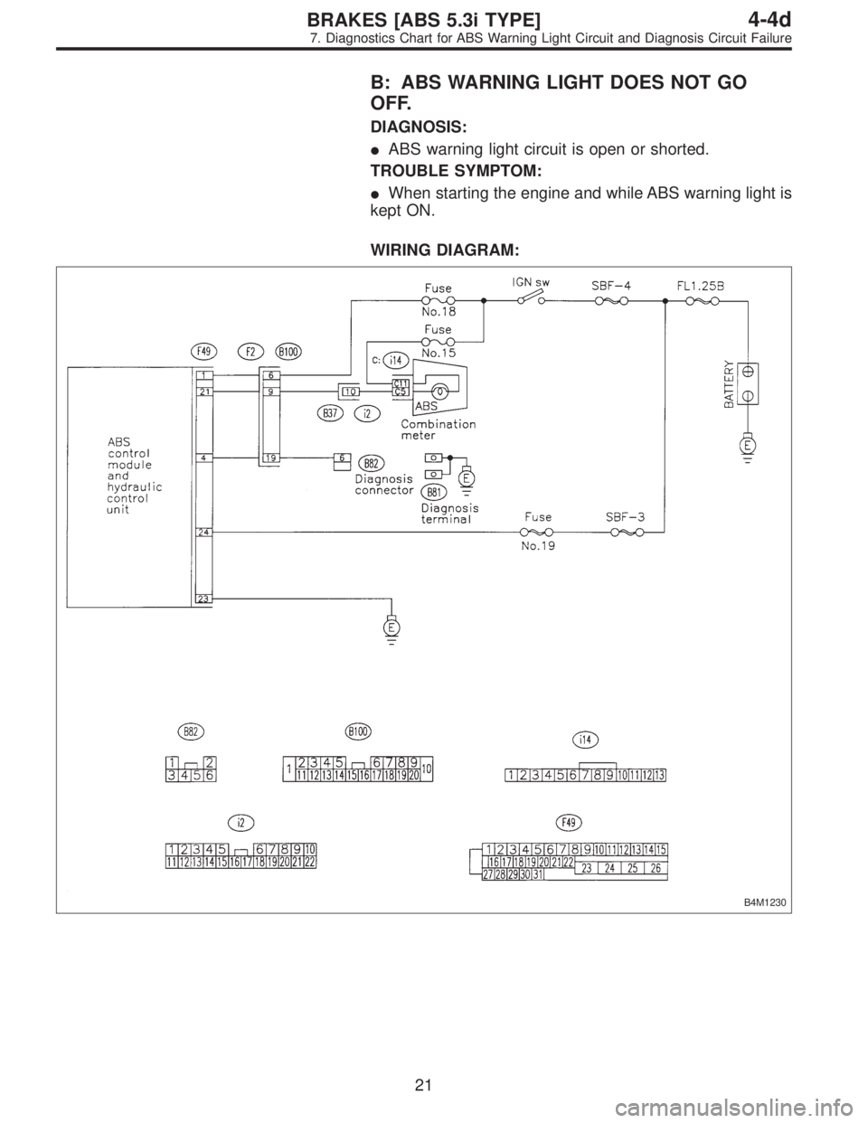
B: ABS WARNING LIGHT DOES NOT GO
OFF.
DIAGNOSIS:
�ABS warning light circuit is open or shorted.
TROUBLE SYMPTOM:
�When starting the engine and while ABS warning light is
kept ON.
WIRING DIAGRAM:
B4M1230
21
4-4dBRAKES [ABS 5.3i TYPE]
7. Diagnostics Chart for ABS Warning Light Circuit and Diagnosis Circuit Failure
Page 2898 of 3342

7B1CHECK INSTALLATION OF ABSCM&H/U
CONNECTOR.
Turn ignition switch to OFF.
: Is ABSCM&H/U connector inserted into
ABSCM until the clamp locks onto it?
: Go to step7B2.
: Insert ABSCM&H/U connector into ABSCM&H/U
until the clamp locks onto it.
B4M0800A
7B2
CHECK DIAGNOSIS TERMINAL.
Measure resistance between diagnosis terminals (B81)
and chassis ground.
: Terminals
Diagnosis terminal (A)—Chassis ground:
Diagnosis terminal (B)—Chassis ground:
Is the resistance less than 0.5Ω?
: Go to step7B3.
: Repair diagnosis terminal harness.
B4M1233A
7B3
CHECK DIAGNOSIS LINE.
1) Turn ignition switch to OFF.
2) Connect diagnosis terminal to diagnosis connector
(B82) No. 6.
3) Disconnect connector from ABSCM&H/U.
4) Measure resistance between ABSCM&H/U connector
and chassis ground.
: Connector & terminal
(F49) No. 4—Chassis ground:
Is the resistance less than 0.5Ω?
: Go to step7B4.
: Repair harness connector between ABSCM&H/U
and diagnosis connector.
22
4-4dBRAKES [ABS 5.3i TYPE]
7. Diagnostics Chart for ABS Warning Light Circuit and Diagnosis Circuit Failure
Page 2899 of 3342
 Start the engine.
2) Idle the engine.
3) Measure voltage between generator and chassis
ground.
Terminal
Generator B terminal (+)—Chassis ground (�):
: Is the voltage")
B4M0430
7B4
CHECK GENERATOR.
1) Start the engine.
2) Idle the engine.
3) Measure voltage between generator and chassis
ground.
Terminal
Generator B terminal (+)—Chassis ground (�):
: Is the voltage between 10 and 15 V?
: Go to step7B5.
: Repair generator.
7B5
CHECK BATTERY TERMINAL.
Turn ignition switch to OFF.
: Is there poor contact at battery terminal?
: Repair battery terminal.
: Go to step7B6.
B4M1234A
7B6
CHECK POWER SUPPLY OF ABSCM.
1) Disconnect connector from ABSCM&H/U.
2) Start engine.
3) Idle the engine.
4) Measure voltage between ABSCM&H/U connector and
chassis ground.
Connector & terminal
(F49) No. 1 (+)—Chassis ground (�):
: Is the voltage between 10 and 15 V?
: Go to step7B7.
: Repair ABSCM&H/U power supply circuit.
7B7
CHECK WIRING HARNESS.
1) Disconnect connector (F2) from connector (B100).
2) Turn ignition switch to ON.
: Does the ABS warning light remain off?
: Go to step7B8.
: Repair front wiring harness.
B4M1235A
7B8
CHECK PROJECTION AT ABSCM&H/U.
1) Turn ignition switch to OFF.
2) Check for broken projection at the ABSCM&H/U termi-
nal.
: Are the projection broken?
: Go to step7B9.
: Replace ABSCM&H/U.
23
4-4dBRAKES [ABS 5.3i TYPE]
7. Diagnostics Chart for ABS Warning Light Circuit and Diagnosis Circuit Failure
Page 2900 of 3342
B4M1237A
7B9
CHECK ABSCM&H/U.
Measure resistance between ABSCM&H/U terminals.
Terminals
No. 21—No. 23:
: Is the resistance more than 1 MΩ?
: Go to step7B10.
: Replace ABSCM&H/U.
B4M1236A
7B10
CHECK WIRING HARNESS.
Measure resistance between connector (F2) and chassis
ground.
Connector & terminal
(F2) No. 9—Chassis ground:
: Is the resistance less than 0.5Ω?
: Go to step7B11.
: Repair harness.
B4M1236A
7B11
CHECK WIRING HARNESS.
1) Connect connector to ABSCM&H/U.
2) Measure resistance between connector (F2) and chas-
sis ground.
Connector & terminal
(F2) No. 9—Chassis ground:
: Is the resistance more than 1 MΩ?
: Go to step7B12.
: Repair harness.
7B12CHECK POOR CONTACT IN ABSCM&H/U
CONNECTOR.
: Is there poor contact in ABSCM&H/U con-
nector?
: Repair connector.
: Replace ABSCM&H/U.
24
4-4dBRAKES [ABS 5.3i TYPE]
7. Diagnostics Chart for ABS Warning Light Circuit and Diagnosis Circuit Failure
.
: Do other warning lights turn on?
: Go to step7A2.
: Repair combination meter.
7A2
CHECK ABS WARNING LIGHT BULB.
1)")
 Turn ignition switch to ON.
2) Measure voltage between connector (B100) and chas-
sis ground.
Connector & terminal
(B100) No. 9 (+)—C")
 Turn ignition switch to OFF.
2) Measure voltage between connector (F2) and chassis
ground.
Connector & terminal
(F2) No. 9 (+)—Chassi")
 and chassis
ground.
Connector & terminal
(F2) No. 9—Chassis ground:
: Is the resistance less than 0.5Ω?
: Go to step7A1")