Page 2727 of 3342
10. Diagnostics Chart with Select
Monitor
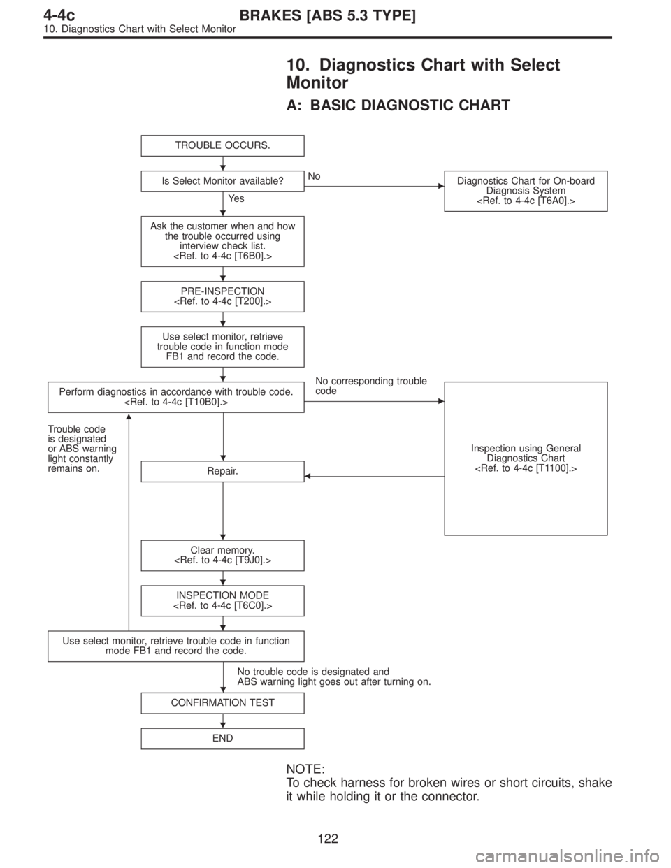
A: BASIC DIAGNOSTIC CHART
TROUBLE OCCURS.
Is Select Monitor available?
Ye s
�No
Diagnostics Chart for On-board
Diagnosis System
Ask the customer when and how
the trouble occurred using
interview check list.
PRE-INSPECTION
Use select monitor, retrieve
trouble code in function mode
FB1 and record the code.
Perform diagnostics in accordance with trouble code.
No corresponding trouble
code
�
Inspection using General
Diagnostics Chart
Trouble code
is designated
or ABS warning
light constantly
remains on.
�
Repair.�
Clear memory.
INSPECTION MODE
Use select monitor, retrieve trouble code in function
mode FB1 and record the code.
No trouble code is designated and
ABS warning light goes out after turning on.
CONFIRMATION TEST
END
NOTE:
To check harness for broken wires or short circuits, shake
it while holding it or the connector.
�
�
�
�
�
�
�
�
�
�
�
122
4-4cBRAKES [ABS 5.3 TYPE]
10. Diagnostics Chart with Select Monitor
Page 2728 of 3342
![SUBARU LEGACY 1997 Service Repair Manual B: LIST OF TROUBLE CODE
Code Display screen (FB1) Contents of diagnosis Ref. to
—ERROR 3 (1) Select monitor communication failure 4-4c [T10C0]
11 NO TROUBLEAlthough no trouble appears on the select](/manual-img/17/57434/w960_57434-2727.png "SUBARU LEGACY 1997 Service Repair Manual B: LIST OF TROUBLE CODE
Code Display screen (FB1) Contents of diagnosis Ref. to
—ERROR 3 (1) Select monitor communication failure 4-4c [T10C0]
11 NO TROUBLEAlthough no trouble appears on the select")
B: LIST OF TROUBLE CODE
Code Display screen (FB1) Contents of diagnosis Ref. to
—ERROR 3 (1) Select monitor communication failure 4-4c [T10C0]
11 NO TROUBLEAlthough no trouble appears on the select monitor display, the ABS
warning light remains on.4-4c [T10D0]
21 FR. SS HARD Open circuit or input voltage too high of FR sensor 4-4c [T10E0]
22 FR. SS SOFT Abnormal ABS sensor signal of FR sensor 4-4c [T10I0]
23 FL. SS HARD Open circuit or input voltage too high of FL sensor 4-4c [T10F0]
24 FL. SS SOFT Abnormal ABS sensor signal of FL sensor 4-4c [T10J0]
25 RR. SS HARD Open circuit or input voltage too high of RR sensor 4-4c [T10G0]
26 RR. SS SOFT Abnormal ABS sensor signal of RR sensor 4-4c [T10K0]
27 RL. SS HARD Open circuit or input voltage too high of RL sensor 4-4c [T10H0]
28 RL. SS SOFT Abnormal ABS sensor signal of RL sensor 4-4c [T10L0]
29 EITHER. SS SOFT Abnormal ABS sensor signal (any one of four) 4-4c [T10M0]
31 FR. EV VALVE Abnormal FR inlet valve 4-4c [T10N0]
32 FR. AV VALVE Abnormal FR outlet valve 4-4c [T10R0]
33 FL. EV VALVE Abnormal FL inlet valve 4-4c [T10O0]
34 FL. AV VALVE Abnormal FL outlet valve 4-4c [T10S0]
35 RR. EV VALVE Abnormal RR inlet valve 4-4c [T10P0]
36 RR. AV VALVE Abnormal RR outlet valve 4-4c [T10T0]
37 RL. EV VALVE Abnormal RL inlet valve 4-4c [T10Q0]
38 RL. AV VALVE Abnormal RL outlet valve 4-4c [T10U0]
41 ECU Abnormal ABSCM 4-4c [T10V0]
42 LOW VOLTAGE Source voltage is low. 4-4c [T10W0]
44CCM LINE A combination of AT control abnormals (ABS not in control) 4-4c [T10X0]
CCM OPEN A combination of AT control abnormals (ABS in control) 4-4c [T10Y0]
46GS POWER OVER G sensor line voltage too high 4-4c [T10Z0]
GS POWER LOW G sensor line voltage too low 4-4c [T10AA0]
51V. RELAY Abnormal valve relay 4-4c [T10AB0]
V. RELAY ON Valve relay ON failure 4-4c [T10AC0]
52M. RELAY OPEN Open circuit of motor relay 4-4c [T10AD0]
M. RELAY ON Motor relay ON failure 4-4c [T10AE0]
MOTOR Abnormal motor 4-4c [T10AF0]
54 BLS Abnormal stop light switch 4-4c [T10AG0]
56G SENSOR LINE Open or short circuit of G sensor 4-4c [T10AH0]
G SENSOR +B Battery short of G sensor 4-4c [T10AI0]
G SENSOR Hµ Abnormal G sensor high µ output 4-4c [T10AJ0]
G SENSOR STICK G sensor output is stuck. 4-4c [T10AK0]
NOTE:
High µ means high friction coefficient against road sur-
face.
123
4-4cBRAKES [ABS 5.3 TYPE]
10. Diagnostics Chart with Select Monitor
Page 2729 of 3342
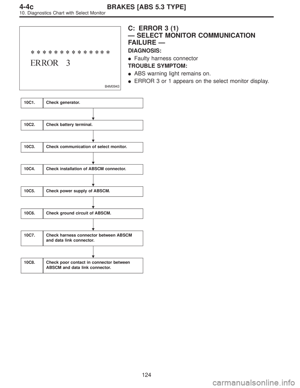
B4M0943
C: ERROR 3 (1)
—SELECT MONITOR COMMUNICATION
FAILURE—
DIAGNOSIS:
�Faulty harness connector
TROUBLE SYMPTOM:
�ABS warning light remains on.
�ERROR 3 or 1 appears on the select monitor display.
10C1.Check generator.
10C2.Check battery terminal.
10C3.Check communication of select monitor.
10C4.Check installation of ABSCM connector.
10C5.Check power supply of ABSCM.
10C6.Check ground circuit of ABSCM.
10C7.Check harness connector between ABSCM
and data link connector.
10C8.Check poor contact in connector between
ABSCM and data link connector.
�
�
�
�
�
�
�
124
4-4cBRAKES [ABS 5.3 TYPE]
10. Diagnostics Chart with Select Monitor
Page 2734 of 3342
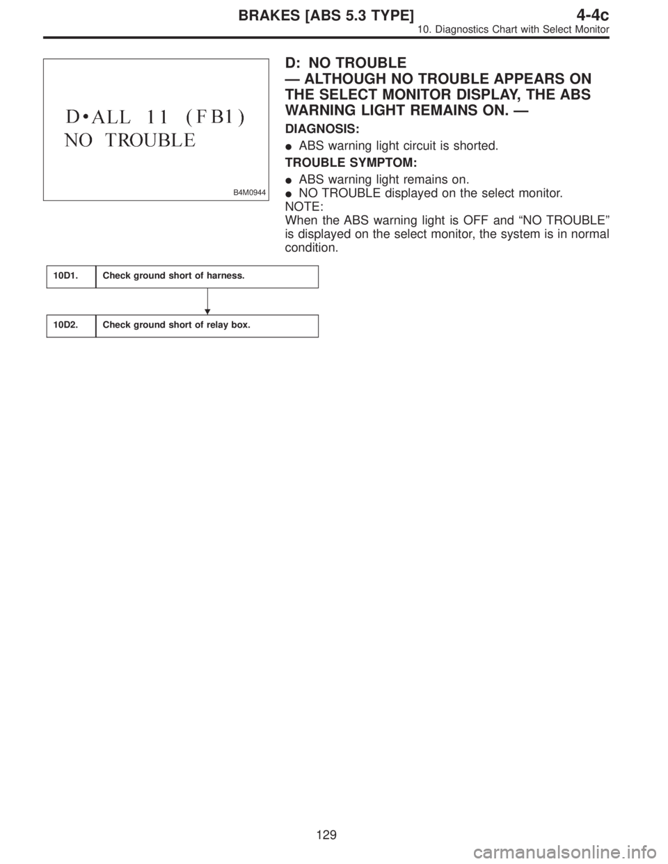
B4M0944
D: NO TROUBLE
—ALTHOUGH NO TROUBLE APPEARS ON
THE SELECT MONITOR DISPLAY, THE ABS
WARNING LIGHT REMAINS ON.—
DIAGNOSIS:
�ABS warning light circuit is shorted.
TROUBLE SYMPTOM:
�ABS warning light remains on.
�NO TROUBLE displayed on the select monitor.
NOTE:
When the ABS warning light is OFF and“NO TROUBLE”
is displayed on the select monitor, the system is in normal
condition.
10D1.Check ground short of harness.
10D2.Check ground short of relay box.
�
129
4-4cBRAKES [ABS 5.3 TYPE]
10. Diagnostics Chart with Select Monitor
Page 2736 of 3342
10D1
CHECK GROUND SHORT OF HARNESS.
1) Turn ignition switch to OFF.
2) Disconnect connector from ABSCM.
3) Disconnect connector (F50) from relay box.
4) Turn ignition switch to ON.
: Does the ABS warning light remain OFF?
: Go to step10D2.
: Repair harness between ABSCM, relay box ABS
warning light.
10D2CHECK GROUND SHORT OF RELAY
BOX.
1) Turn ignition switch to OFF.
2) Connect connector (F50) to relay box.
3) Disconnect connector (ABS1) from hydraulic unit.
4) Remove valve relay from relay box.
5) Turn ignition switch to ON.
: Does the ABS warning light remain OFF?
: Replace ABSCM.
: Replace relay box.
131
4-4cBRAKES [ABS 5.3 TYPE]
10. Diagnostics Chart with Select Monitor
Page 2851 of 3342
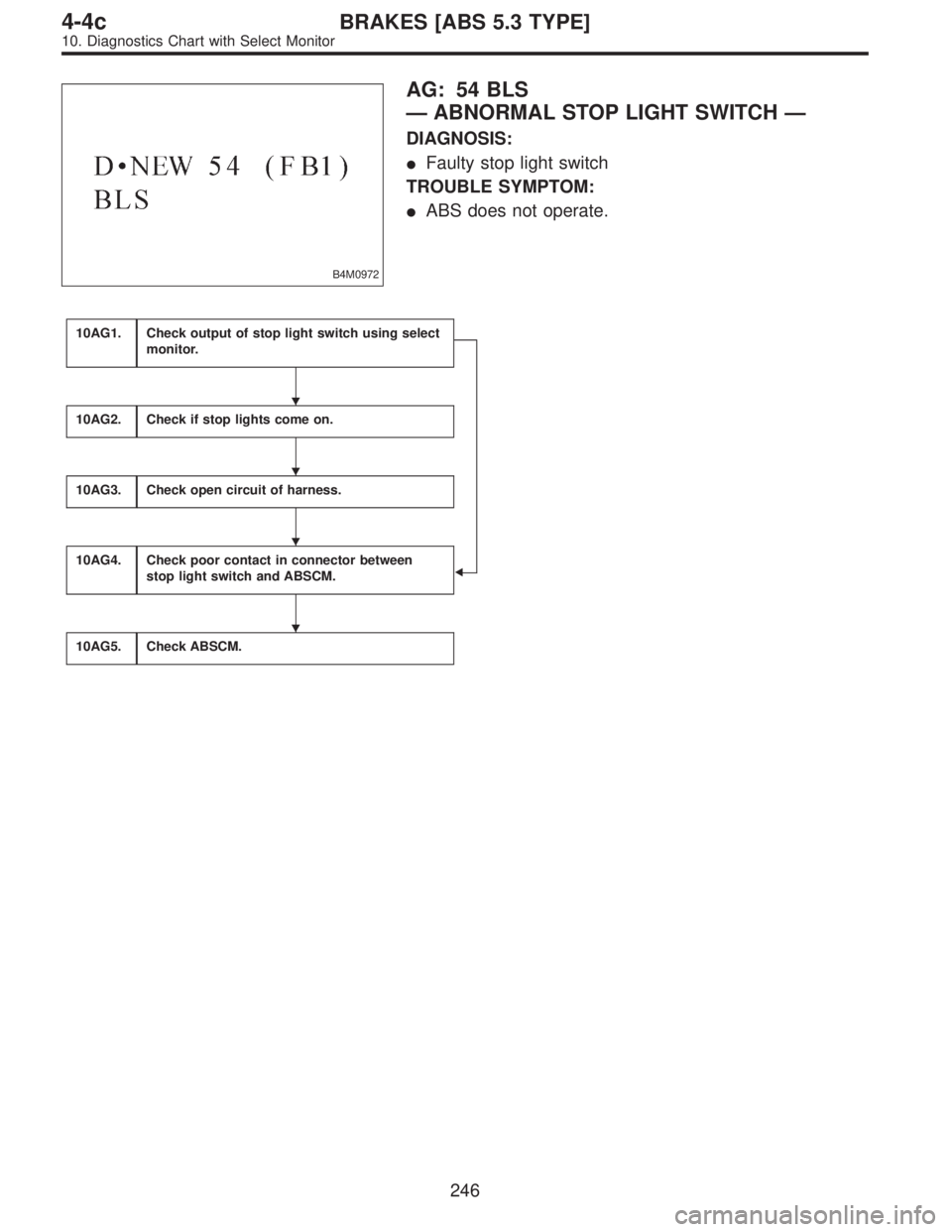
B4M0972
AG: 54 BLS
—ABNORMAL STOP LIGHT SWITCH—
DIAGNOSIS:
�Faulty stop light switch
TROUBLE SYMPTOM:
�ABS does not operate.
10AG1.Check output of stop light switch using select
monitor.
�
10AG2.Check if stop lights come on.
10AG3.Check open circuit of harness.
10AG4.Check poor contact in connector between
stop light switch and ABSCM.
10AG5.Check ABSCM.
�
�
�
�
246
4-4cBRAKES [ABS 5.3 TYPE]
10. Diagnostics Chart with Select Monitor
Page 2853 of 3342
 Press
F,
0and
9on the select monitor.
2) Depress the brake pedal.
3) Read the stop light switch output on the select monitor
dis")
B4M0973
10AG1CHECK OUTPUT OF STOP LIGHT
SWITCH USING SELECT MONITOR.
1) Press
F,
0and
9on the select monitor.
2) Depress the brake pedal.
3) Read the stop light switch output on the select monitor
display.
: Is the reading indicated on monitor display
less than 1.5 V?
: Go to next step.
: Go to step10AG1.
4) Release the brake pedal.
5) Read the stop light switch output on the select monitor
display.
: Is the reading indicated on monitor display
greater than 4.5 V?
: Go to step10AG4.
: Go to step10AG2.
10AG2
CHECK IF STOP LIGHTS COME ON.
Depress the brake pedal.
: Do stop lights turn on?
: Go to step10AG3.
: Repair stop lights circuit.
B4M0908A
10AG3
CHECK OPEN CIRCUIT OF HARNESS.
1) Turn ignition switch to OFF.
2) Disconnect connector from ABSCM.
3) Depress brake pedal.
4) Measure voltage between ABSCM connector and chas-
sis ground.
: Connector & terminal
(F49) No. 36—Chassis ground
Is voltage 10—13 V?
: Go to step10AG4.
: Repair harness between stop light switch and
ABSCM.
248
4-4cBRAKES [ABS 5.3 TYPE]
10. Diagnostics Chart with Select Monitor
Page 2854 of 3342
10AG4CHECK POOR CONTACT IN CONNEC-
TOR BETWEEN STOP LIGHT SWITCH
AND ABSCM.
: Is there poor contact in connector between
stop light switch and ABSCM?
: Repair connector.
: Go to step10AG5.
10AG5
CHECK ABSCM.
1) Connect all connectors.
2) Erase the memory.
3) Perform inspection mode.
4) Read out the trouble code.
: Is the same trouble code as in the current
diagnosis still being output?
: Replace ABSCM.
: Go to next.
: Are other trouble codes being output?
: Proceed with the diagnosis corresponding to the
trouble code.
: A temporary poor contact.
249
4-4cBRAKES [ABS 5.3 TYPE]
10. Diagnostics Chart with Select Monitor
 Turn ignition switch to OFF.
2) Disconnect connector from ABSCM.
3) Disconnect connector (F50) from relay box.
4) Turn ignition switch to ON.
: Does the ABS warn")