Page 1671 of 3342
G5M0323
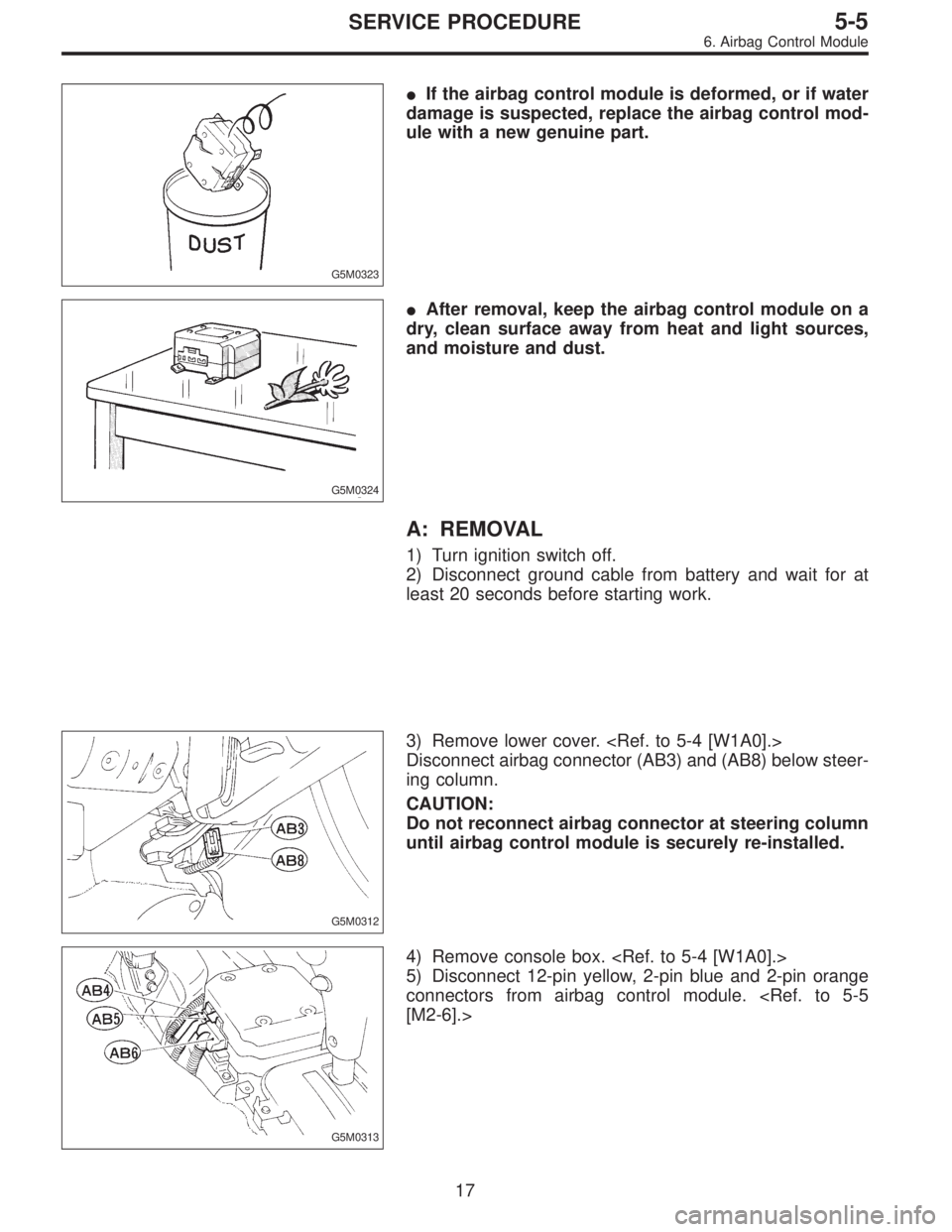
�If the airbag control module is deformed, or if water
damage is suspected, replace the airbag control mod-
ule with a new genuine part.
G5M0324
�After removal, keep the airbag control module on a
dry, clean surface away from heat and light sources,
and moisture and dust.
A: REMOVAL
1) Turn ignition switch off.
2) Disconnect ground cable from battery and wait for at
least 20 seconds before starting work.
G5M0312
3) Remove lower cover.
Disconnect airbag connector (AB3) and (AB8) below steer-
ing column.
CAUTION:
Do not reconnect airbag connector at steering column
until airbag control module is securely re-installed.
G5M0313
4) Remove console box.
5) Disconnect 12-pin yellow, 2-pin blue and 2-pin orange
connectors from airbag control module.
[M2-6].>
17
5-5SERVICE PROCEDURE
6. Airbag Control Module
Page 1672 of 3342
 Using TORX®BIT T40 (Tamper resistant type), remove
two TORX®bolts.
Discard the old TORX®bolts.
CAUTION:
Use new TORX
®bolts during re-assembly.
B: INSTALLATION
Installation is in revers")
B5M0105
6) Using TORX®BIT T40 (Tamper resistant type), remove
two TORX®bolts.
Discard the old TORX®bolts.
CAUTION:
Use new TORX
®bolts during re-assembly.
B: INSTALLATION
Installation is in reverse order of removal procedures.
CAUTION:
Be sure to fully secure all airbag system connectors
during re-assembly and confirm that all green double
lock mechanisms are engaged.
7. Combination Switch
A: REMOVAL
1) Turn ignition switch off.
2) Disconnect ground cable from battery and wait for at
least 20 seconds before starting work.
G5M0312
3) Remove lower cover. Disconnect
airbag connector (AB3) and (AB8) below steering column.
CAUTION:
Do not reconnect airbag connector at steering column
until combination switch is securely re-installed.
4) Disconnect combination switch connectors from body
harness connector.
H5M0662A
5) Set front wheels in straight ahead position. Using
TORX®BIT T30, remove two TORX®bolts.
18
5-5SERVICE PROCEDURE
6. Airbag Control Module - 7. Combination Switch
Page 1673 of 3342
 Using TORX®BIT T40 (Tamper resistant type), remove
two TORX®bolts.
Discard the old TORX®bolts.
CAUTION:
Use new TORX
®bolts during re-assembly.
B: INSTALLATION
Installation is in revers")
B5M0105
6) Using TORX®BIT T40 (Tamper resistant type), remove
two TORX®bolts.
Discard the old TORX®bolts.
CAUTION:
Use new TORX
®bolts during re-assembly.
B: INSTALLATION
Installation is in reverse order of removal procedures.
CAUTION:
Be sure to fully secure all airbag system connectors
during re-assembly and confirm that all green double
lock mechanisms are engaged.
7. Combination Switch
A: REMOVAL
1) Turn ignition switch off.
2) Disconnect ground cable from battery and wait for at
least 20 seconds before starting work.
G5M0312
3) Remove lower cover. Disconnect
airbag connector (AB3) and (AB8) below steering column.
CAUTION:
Do not reconnect airbag connector at steering column
until combination switch is securely re-installed.
4) Disconnect combination switch connectors from body
harness connector.
H5M0662A
5) Set front wheels in straight ahead position. Using
TORX®BIT T30, remove two TORX®bolts.
18
5-5SERVICE PROCEDURE
6. Airbag Control Module - 7. Combination Switch
Page 1674 of 3342
H5M0664
6) Disconnect airbag connector on back of airbag module.
Remove airbag module, and place it
with pad side facing upward.
G5M0332
7) Using steering puller, remove steering wheel.
CAUTION:
Do not allow connector to interfere when removing
steering wheel.
B5M0106
8) Remove steering column covers.
9) Removing two retaining screws, remove combination
switch.
B: ADJUSTMENT
1. CENTERING ROLL CONNECTOR
Before installing steering wheel, make sure to center roll
connector built into combination switch.
1) Make sure that front wheels are positioned straight
ahead.
2) Install steering gearbox, steering shaft and combination
switch properly. Turn roll connector pin�
1clockwise until
it stops.
H5M0663A
3) Then, back off roll connector pin�1approximately 2.65
turns until“�”marks aligned.
19
5-5SERVICE PROCEDURE
7. Combination Switch
Page 1675 of 3342
H5M0663A
C: INSTALLATION
1) Before installing combination switch, check to ensure
that combination switch is off and front wheels are set in
the straight ahead position.
CAUTION:
Failure to do this might damage roll connector.
2) Install column cover and center roll connector.
3) Install steering wheel in neutral position. Carefully insert
roll connector pin�
1into hole on steering wheel.
NOTE:
If steering wheel angle requires fine adjustment, adjust tie-
rod.
4) Install airbag module and lower cover in the reverse
order of removal.
20
5-5SERVICE PROCEDURE
7. Combination Switch
Page 1683 of 3342
.
�The designated trouble code is output during self-diag-
nosis. (Refer t")
6. COMBINATION SWITCH
Inspection standard:
�A vehicle damaged in a collision (regardless of whether
or not airbag is deployed).
�The designated trouble code is output during self-diag-
nosis. (Refer to“Diagnostics”Section.)
Replacement standard:
�Combination switch or steering roll connector is
deformed or cracked.
B5M0095
7. STEERING WHEEL
Inspection standard:
�A vehicle damaged in a collision (regardless of whether
or not airbag is deployed).
Replacement standard:
�Check steering wheel insert for cracks or deformities.
�Check to ensure that new airbag module is properly
installed in steering wheel.
�After installing airbag module, check to ensure that it is
free of interference with steering wheel and that clearance
between the two is equal at all points.
B5M0096A
8. STEERING COLUMN ASSEMBLY
Inspection standard:
�A vehicle damaged in a collision (regardless of whether
or not airbag is deployed).
Replacement standard:
�Check steering wheel free play in axial and radial direc-
tions.
Specifications:
Axial free play A
Less than ±6 mm (0.24 in)
Radial free play L
Less than ±7 mm (0.28 in)
8
5-5bSERVICE PROCEDURE
2. Inspection and Replacement Standards
Page 1684 of 3342
B5M0097A
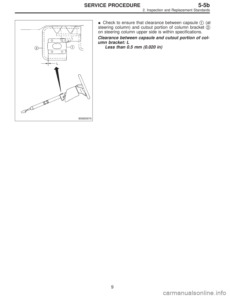
�Check to ensure that clearance between capsule�1(at
steering column) and cutout portion of column bracket�
2
on steering column upper side is within specifications.
Clearance between capsule and cutout portion of col-
umn bracket: L
Less than 0.5 mm (0.020 in)
9
5-5bSERVICE PROCEDURE
2. Inspection and Replacement Standards
Page 1688 of 3342
B5M0098
2) Remove four bolts and then carefully remove airbag
module.
3) Refer to“CAUTION”for handling of a removed airbag
module.
B: INSTALLATION
Installation is in reverse order of removal procedures.
Observe the following: Make sure that ignition switch is off.
CAUTION:
Do not allow harness and connectors to interfere or
get caught with other parts.
4. Main Harness
A: REMOVAL
1) Turn ignition switch off.
2) Disconnect ground cable from battery and wait for at
least 20 seconds before starting work.
G5M0312
3) Remove lower cover.
Disconnect airbag connector (AB3) and (AB8) below steer-
ing column.
CAUTION:
Do not reconnect airbag connector at steering column
until main harness are securely re-installed.
G5M0313
4) Remove console box. Discon-
nect 12-pin yellow connector (AB6) from airbag control
module.
13
5-5bSERVICE PROCEDURE
3. Airbag Module - 4. Main Harness
![SUBARU LEGACY 1997 Service Repair Manual H5M0664
6) Disconnect airbag connector on back of airbag module.
<Ref. to 5-5 [M2-6].> Remove airbag module, and place it
with pad side facing upward. <Ref. to 5-5 [W300].>
G5M0332
7) Using steering p](/manual-img/17/57434/w960_57434-1673.png "SUBARU LEGACY 1997 Service Repair Manual H5M0664
6) Disconnect airbag connector on back of airbag module.
<Ref. to 5-5 [M2-6].> Remove airbag module, and place it
with pad side facing upward. <Ref. to 5-5 [W300].>
G5M0332
7) Using steering p")
 Before installing combination switch, check to ensure
that combination switch is off and front wheels are set in
the straight ahead position.
CAUTION:
Failure to do this mi")
 Remove four bolts and then carefully remove airbag
module.
3) Refer to“CAUTION”for handling of a removed airbag
module.
B: INSTALLATION
Installation is in reverse order of removal proce")