Page 1689 of 3342
B5M0098
2) Remove four bolts and then carefully remove airbag
module.
3) Refer to“CAUTION”for handling of a removed airbag
module.
B: INSTALLATION
Installation is in reverse order of removal procedures.
Observe the following: Make sure that ignition switch is off.
CAUTION:
Do not allow harness and connectors to interfere or
get caught with other parts.
4. Main Harness
A: REMOVAL
1) Turn ignition switch off.
2) Disconnect ground cable from battery and wait for at
least 20 seconds before starting work.
G5M0312
3) Remove lower cover.
Disconnect airbag connector (AB3) and (AB8) below steer-
ing column.
CAUTION:
Do not reconnect airbag connector at steering column
until main harness are securely re-installed.
G5M0313
4) Remove console box. Discon-
nect 12-pin yellow connector (AB6) from airbag control
module.
13
5-5bSERVICE PROCEDURE
3. Airbag Module - 4. Main Harness
Page 1692 of 3342
G5M0323
�If the airbag control module is deformed, or if water
damage is suspected, replace the airbag control mod-
ule with a new genuine part.
G5M0324
�After removal, keep the airbag control module on a
dry, clean surface away from heat and light sources,
and moisture and dust.
A: REMOVAL
1) Turn ignition switch off.
2) Disconnect ground cable from battery and wait for at
least 20 seconds before starting work.
G5M0312
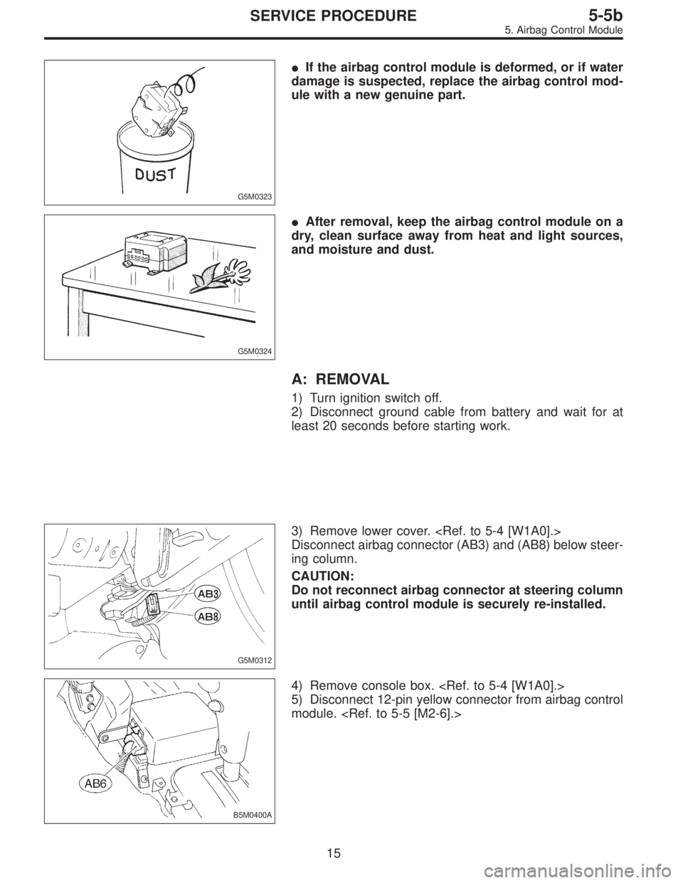
3) Remove lower cover.
Disconnect airbag connector (AB3) and (AB8) below steer-
ing column.
CAUTION:
Do not reconnect airbag connector at steering column
until airbag control module is securely re-installed.
B5M0400A
4) Remove console box.
5) Disconnect 12-pin yellow connector from airbag control
module.
15
5-5bSERVICE PROCEDURE
5. Airbag Control Module
Page 1693 of 3342
 Using TORX®BIT T40 (Tamper resistant type), remove
two TORX®bolts.
Discard the old TORX®bolts.
CAUTION:
Use new TORX
®bolts during re-assembly.
B: INSTALLATION
Installation is in revers")
B5M0105
6) Using TORX®BIT T40 (Tamper resistant type), remove
two TORX®bolts.
Discard the old TORX®bolts.
CAUTION:
Use new TORX
®bolts during re-assembly.
B: INSTALLATION
Installation is in reverse order of removal procedures.
CAUTION:
Be sure to fully secure all airbag system connectors
during re-assembly and confirm that all green double
lock mechanisms are engaged.
6. Combination Switch
A: REMOVAL
1) Turn ignition switch off.
2) Disconnect ground cable from battery and wait for at
least 20 seconds before starting work.
G5M0312
3) Remove lower cover. Disconnect
airbag connector (AB3) and (AB8) below steering column.
CAUTION:
Do not reconnect airbag connector at steering column
until combination switch is securely re-installed.
4) Disconnect combination switch connectors from body
harness connector.
H5M0662A
5) Set front wheels in straight ahead position. Using
TORX®BIT T30, remove two TORX®bolts.
16
5-5bSERVICE PROCEDURE
5. Airbag Control Module - 6. Combination Switch
Page 1694 of 3342
 Using TORX®BIT T40 (Tamper resistant type), remove
two TORX®bolts.
Discard the old TORX®bolts.
CAUTION:
Use new TORX
®bolts during re-assembly.
B: INSTALLATION
Installation is in revers")
B5M0105
6) Using TORX®BIT T40 (Tamper resistant type), remove
two TORX®bolts.
Discard the old TORX®bolts.
CAUTION:
Use new TORX
®bolts during re-assembly.
B: INSTALLATION
Installation is in reverse order of removal procedures.
CAUTION:
Be sure to fully secure all airbag system connectors
during re-assembly and confirm that all green double
lock mechanisms are engaged.
6. Combination Switch
A: REMOVAL
1) Turn ignition switch off.
2) Disconnect ground cable from battery and wait for at
least 20 seconds before starting work.
G5M0312
3) Remove lower cover. Disconnect
airbag connector (AB3) and (AB8) below steering column.
CAUTION:
Do not reconnect airbag connector at steering column
until combination switch is securely re-installed.
4) Disconnect combination switch connectors from body
harness connector.
H5M0662A
5) Set front wheels in straight ahead position. Using
TORX®BIT T30, remove two TORX®bolts.
16
5-5bSERVICE PROCEDURE
5. Airbag Control Module - 6. Combination Switch
Page 1695 of 3342
H5M0664
6) Disconnect airbag connector on back of airbag module.
Remove airbag module, and place it
with pad side facing upward.
G5M0332
7) Using steering puller, remove steering wheel.
CAUTION:
Do not allow connector to interfere when removing
steering wheel.
B5M0106
8) Remove steering column covers.
9) Removing two retaining screws, remove combination
switch.
B: ADJUSTMENT
1. CENTERING ROLL CONNECTOR
Before installing steering wheel, make sure to center roll
connector built into combination switch.
1) Make sure that front wheels are positioned straight
ahead.
2) Install steering gearbox, steering shaft and combination
switch properly. Turn roll connector pin�
1clockwiseuntil
it stops.
H5M0663A
3) Then, back off roll connector pin�1approximately 2.65
turns until“�”marks aligned.
17
5-5bSERVICE PROCEDURE
6. Combination Switch
Page 1696 of 3342
H5M0663A
C: INSTALLATION
1) Before installing combination switch, check to ensure
that combination switch is off and front wheels are set in
the straight ahead position.
CAUTION:
Failure to do this might damage roll connector.
2) Install column cover and center roll connector.
3) Install steering wheel in neutral position. Carefully insert
roll connector pin�
1into hole on steering wheel.
NOTE:
If steering wheel angle requires fine adjustment, adjust tie-
rod.
4) Install airbag module and lower cover in the reverse
order of removal.
18
5-5bSERVICE PROCEDURE
6. Combination Switch
Page 1749 of 3342
![SUBARU LEGACY 1997 Service Repair Manual B6M0236
3. COMBINATION SWITCH (WITHOUT AIRBAG
MODEL)
Refer to 5-5 [W7A0] as for removal of combination
switch on airbag equipped model.
1) Remove steering wheel. <Ref. to 4-3 [W2A0].>
2) Remove screws](/manual-img/17/57434/w960_57434-1748.png "SUBARU LEGACY 1997 Service Repair Manual B6M0236
3. COMBINATION SWITCH (WITHOUT AIRBAG
MODEL)
Refer to 5-5 [W7A0] as for removal of combination
switch on airbag equipped model.
1) Remove steering wheel. <Ref. to 4-3 [W2A0].>
2) Remove screws")
B6M0236
3. COMBINATION SWITCH (WITHOUT AIRBAG
MODEL)
Refer to 5-5 [W7A0] as for removal of combination
switch on airbag equipped model.
1) Remove steering wheel.
2) Remove screws which secure upper column cover to
lower column cover.
3) Remove screws which secure knee protector and
remove knee protector.
CAUTION:
When installing knee protector, ensure that harness is
not caught by adjacent parts.
4) Disconnect connector from body harness and undo
holddown band.
G6M0107
5) Remove screws which secure switch and remove
switch.
CAUTION:
During installation (with key interlock)
�When routing combination switch harness around
steering system, do not place it over key interlock
release knob.
�After installing lower column cover, ensure that key
interlock release knob is accessible.
B6M0237
C: DISASSEMBLY AND ASSEMBLY
1. COMBINATION SWITCH
1) Remove screws which secure slip ring to combination
switch, and remove slip ring.
G6M0109
2) Remove screws which secure lighting switch, wiper and
washer switch. Remove both switches.
Assembly is in the reverse order of disassembly.
11
6-2SERVICE PROCEDURE
4. Headlight
Page 1774 of 3342
 When tester indicates 12 volts when its probe reaches
point“A”, a broken circuit occurs between point“A”and the
negative terminal. Slowly move tester probe toward the
negative termi")
G6M0137
4) When tester indicates 12 volts when its probe reaches
point“A”, a broken circuit occurs between point“A”and the
negative terminal. Slowly move tester probe toward the
negative terminal while contacting it on heat wire to locate
point where tester indication changes abruptly (0 volts).
This is the point where a broken circuit occurs.
When tester indicates 0 volts when its probe reaches point
“A”, a broken circuit occurs between point“A”and the posi-
tive terminal. Locate a point where tester indication
changes abruptly (12 volts) while slowly moving tester
probe toward the positive terminal.
G6M0138
C: REPAIR
1) Clean broken wire and its surrounding area.
2) Cut off slit on (used) thin film by 0.5 mm (0.020 in) width
and 10 mm (0.39 in) length.
3) Place the slit on glass along the broken wire, and
deposit conductive silver composition (DUPONT No. 4817)
on the broken portion.
4) Dry out the deposited portion.
5) Inspect the repaired wire for continuity.
B6M0120
13. Combination Meter
A: REMOVAL AND INSTALLATION
1. COMBINATION METER
1) Move steering wheel fully down.
2) Remove screws which secure meter visor.
3) Remove visor from instrument panel.
4) Disconnect connectors from meter visor.
B6M0121
5) Remove screws which secure combination meter, and
pull combination meter out.
6) Disconnect connectors from back of combination meter.
CAUTION:
When installing combination meter, be sure to connect
connectors to backside of combination meter.
33
6-2SERVICE PROCEDURE
12. Rear Window Defogger - 13. Combination Meter
 Remove four bolts and then carefully remove airbag
module.
3) Refer to“CAUTION”for handling of a removed airbag
module.
B: INSTALLATION
Installation is in reverse order of removal proce")
![SUBARU LEGACY 1997 Service Repair Manual H5M0664
6) Disconnect airbag connector on back of airbag module.
<Ref. to 5-5 [M2-6].> Remove airbag module, and place it
with pad side facing upward. <Ref. to 5-5b [W300].>
G5M0332
7) Using steering](/manual-img/17/57434/w960_57434-1694.png "SUBARU LEGACY 1997 Service Repair Manual H5M0664
6) Disconnect airbag connector on back of airbag module.
<Ref. to 5-5 [M2-6].> Remove airbag module, and place it
with pad side facing upward. <Ref. to 5-5b [W300].>
G5M0332
7) Using steering")
 Before installing combination switch, check to ensure
that combination switch is off and front wheels are set in
the straight ahead position.
CAUTION:
Failure to do this mi")