Page 3126 of 3342
G5M0312
3. DOUBLE LOCK INSPECTION FOR CONNECTORS
(AB3) AND (AB8)
1) Remove lower cover panel.
2) Check double lock of connectors (AB3) and (AB8)
below steering column.
: Is there poor contact in double lock of con-
nectors (AB3) and (AB8)?
: Repair poor contact in double lock of connectors
(AB3) and (AB8).
: Go to step4.
H5M0664
4. ROLL CONNECTOR DOUBLE LOCK INSPECTION
AT CONNECTORS (AB2) AND (AB7)
Remove driver side airbag module ,
and check double lock of connectors (AB2) and (AB7) at
roll connector.
: Is there poor contact in double lock of con-
nectors (AB2) and (AB7)?
: Repair poor contact in double lock of connectors
(AB2) and (AB7).
: Replace airbag control module.
23
5-5bSUPPLEMENTAL RESTRAINT SYSTEM (ELECTRIC SENSOR TYPE)
5. Diagnostics Chart with Trouble Code
Page 3140 of 3342

B5M0122B
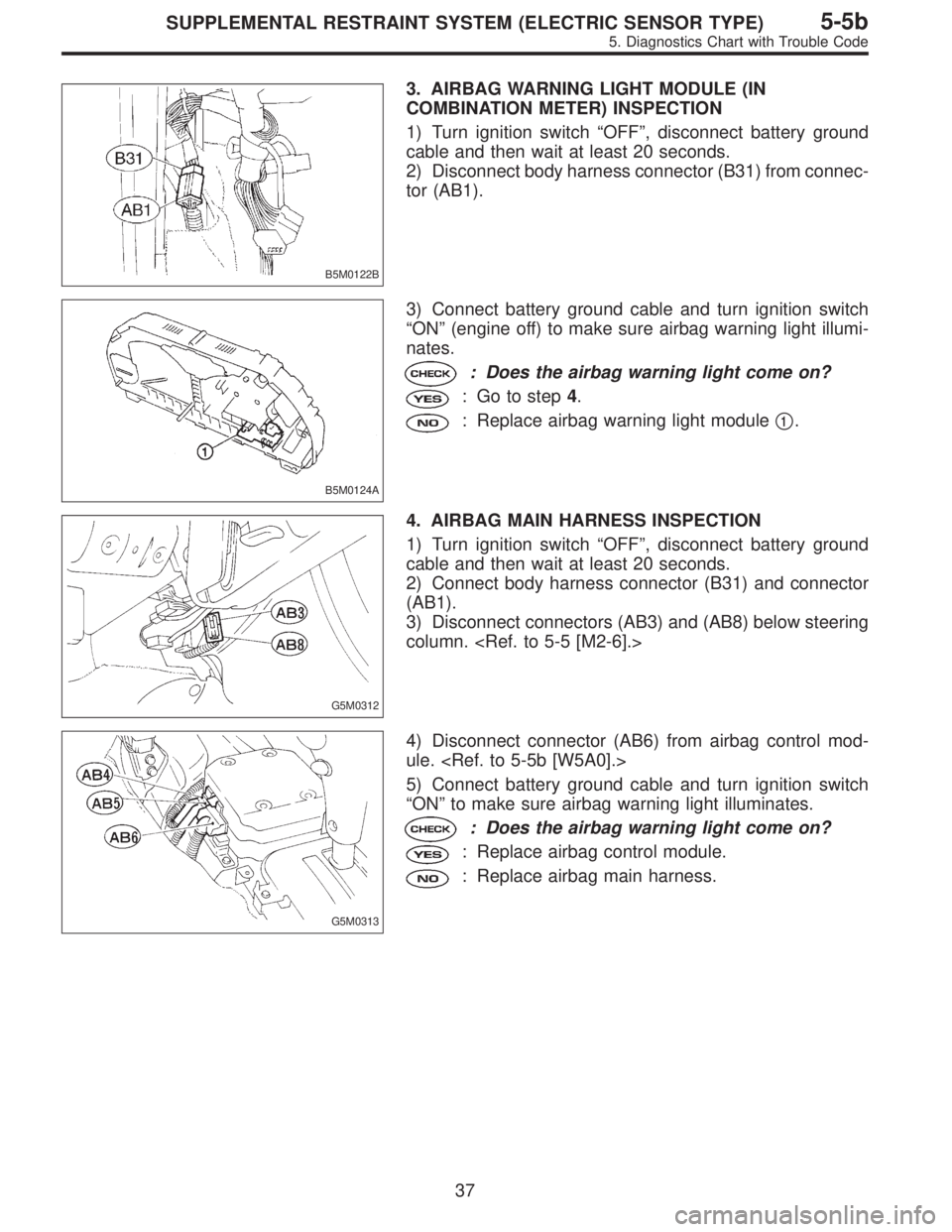
3. AIRBAG WARNING LIGHT MODULE (IN
COMBINATION METER) INSPECTION
1) Turn ignition switch“OFF”, disconnect battery ground
cable and then wait at least 20 seconds.
2) Disconnect body harness connector (B31) from connec-
tor (AB1).
B5M0124A
3) Connect battery ground cable and turn ignition switch
“ON”(engine off) to make sure airbag warning light illumi-
nates.
: Does the airbag warning light come on?
: Go to step4.
: Replace airbag warning light module�1.
G5M0312
4. AIRBAG MAIN HARNESS INSPECTION
1) Turn ignition switch“OFF”, disconnect battery ground
cable and then wait at least 20 seconds.
2) Connect body harness connector (B31) and connector
(AB1).
3) Disconnect connectors (AB3) and (AB8) below steering
column.
G5M0313
4) Disconnect connector (AB6) from airbag control mod-
ule.
5) Connect battery ground cable and turn ignition switch
“ON”to make sure airbag warning light illuminates.
: Does the airbag warning light come on?
: Replace airbag control module.
: Replace airbag main harness.
37
5-5bSUPPLEMENTAL RESTRAINT SYSTEM (ELECTRIC SENSOR TYPE)
5. Diagnostics Chart with Trouble Code
Page 3143 of 3342

3) Conduct appearance inspection on parts selected.
: Is there anything unusual about the appear-
ance of airbag component parts?
: Replace faulty airbag component parts.
: Go to step2.
NOTE:
Also check connector terminals, wiring harness, case, etc.
for damage.
2. AIRBAG COMPONENT PARTS VIBRATION
INSPECTION
1) Gently shake check parts (to determine faults.).
2) To check airbag module or roll connector, turn and tilt
steering wheel.
CAUTION:
Do not shake or vibrate airbag control module.
: Does the component malfunction again
when shaking?
: Replace faulty airbag component parts.
: Go to step3.
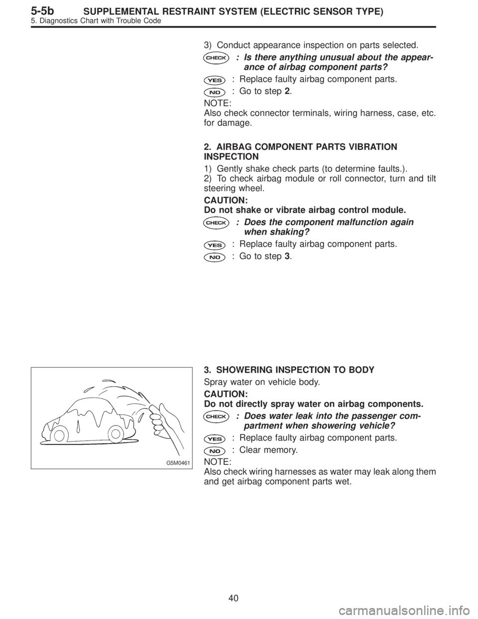
G5M0461
3. SHOWERING INSPECTION TO BODY
Spray water on vehicle body.
CAUTION:
Do not directly spray water on airbag components.
: Does water leak into the passenger com-
partment when showering vehicle?
: Replace faulty airbag component parts.
: Clear memory.
NOTE:
Also check wiring harnesses as water may leak along them
and get airbag component parts wet.
40
5-5bSUPPLEMENTAL RESTRAINT SYSTEM (ELECTRIC SENSOR TYPE)
5. Diagnostics Chart with Trouble Code
Page 3331 of 3342

�In this manual, the following symbols are used.
*: Selective part
�: Replacement part
: Should be lubricated with oil.
: Should be lubricated with grease.
: Sealing point
: Tightening torque
�WARNING, CAUTION, NOTE
�WARNING: Indicates the item which must be observed precisely during performance of maintenance ser-
vices in order to avoid injury to the mechanics and other persons.
�CAUTION: Indicates the item which must be followed precisely during performance of maintenance ser-
vices so as to avoid damage and breakage to the vehicle and its parts and components.
�NOTE: Indicates the hints, knacks, etc. which make the maintenance job easier.
�SPECIAL TOOLS
When any special tool is required to perform the job, it is identified by“ST”in the applicable illustration and its
part number is shown in the manual.
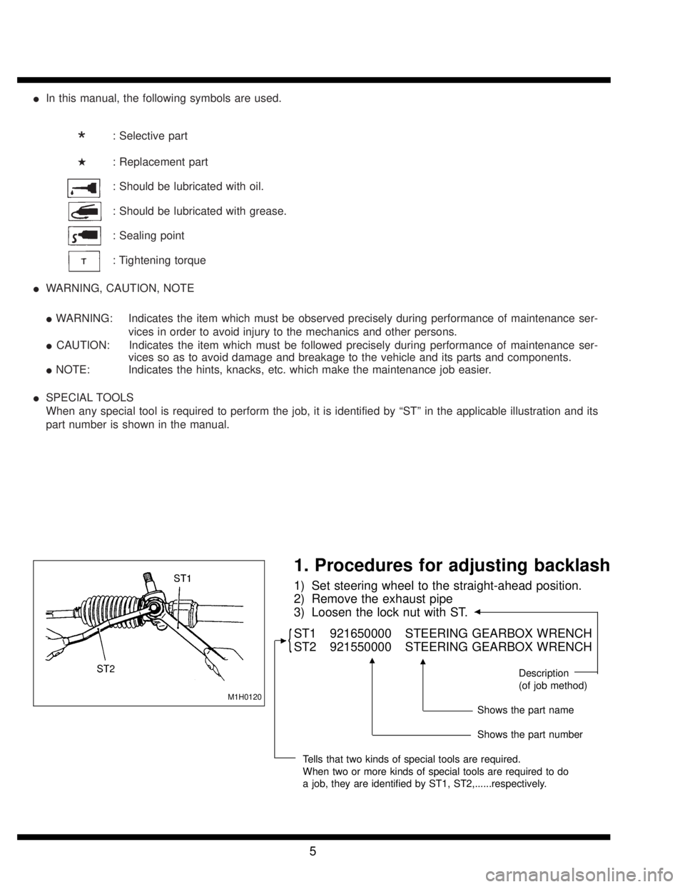
M1H0120
1. Procedures for adjusting backlash
1) Set steering wheel to the straight-ahead position.
2) Remove the exhaust pipe
3) Loosen the lock nut with ST.
�
{ST1 921650000 STEERING GEARBOX WRENCH
ST2 921550000 STEERING GEARBOX WRENCH
Description
(of job method)
Shows the part name
Shows the part number
Tells that two kinds of special tools are required.
When two or more kinds of special tools are required to do
a job, they are identified by ST1, ST2,......respectively.
�
��
5