Page 1487 of 3342
/98N (10 kg, 22 lb)
G4M0939
AB
*New belt:
7.0—9.0
(0.276—0.354)
Existing belt:
9.0—11.0
(0.354—0.433)*New belt:
7.5—8.5
(0.295—0.335)
Existing belt:
9.0�")
Pulley arrangement Tension mm (in)/98N (10 kg, 22 lb)
G4M0939
AB
*New belt:
7.0—9.0
(0.276—0.354)
Existing belt:
9.0—11.0
(0.354—0.433)*New belt:
7.5—8.5
(0.295—0.335)
Existing belt:
9.0—10.0
(0.354—0.394)
* When replacing belts with new ones, adjust tensions to
specification and then readjust to the same specification
after running engine for 5 minutes.
Figures in table refer to the number of grooves in pulleys.
C/P : Crankshaft pulley
ALT : Alternator pulley
P/S : Power steering oil pump pulley
A/C : Air conditioner compressor pulley
I/P : Idler pulley
G4M0634
CAUTION:
�Ensure that the V-belt is aligned correctly. If it is not,
check for loose bolts.
�The V-belt should not be too tight or too loose.
A belt which is too tight may break bearing or cause
gas to leak from the shaft seal. A belt which is too
loose slips, thereby causing the belt cut.
�After completing the compressor installation and
testing the system operation, check and adjust the ten-
sion of both V-belts again.
B4M0761A
7) Install high-pressure hose�2(Flexible hose Pd).
Connect high-pressure hose with compressor.
CAUTION:
Be sure to apply compressor oil to the periphery of
O-ring.
B4M0761A
8) Install low-pressure hose�1(Flexible hose Ps).
Connect low-pressure hose with compressor.
CAUTION:
Be sure to apply compressor oil to the periphery of
O-ring.
33
4-7SERVICE PROCEDURE
11. Compressor
Page 1538 of 3342
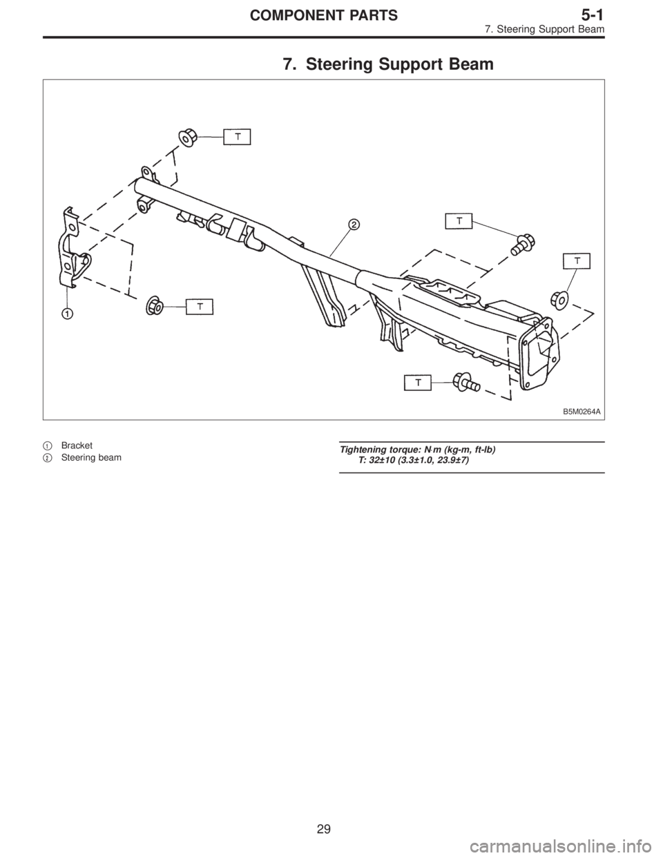
7. Steering Support Beam
B5M0264A
�1Bracket
�
2Steering beamTightening torque: N⋅m (kg-m, ft-lb)
T: 32±10 (3.3±1.0, 23.9±7)
29
5-1COMPONENT PARTS
7. Steering Support Beam
Page 1649 of 3342
B5M0026
7) Remove cover back panel.
G5M0278
8) Remove two bolts and lower steering column.
B5M0027
9) Set temperature control lever to Max. COLD position,
and then disconnect temperature control cable from link of
heater module.
NOTE:
Do not move lever and link when installing.
B5M0028
10) Remove bolt cover and bolt of both side.
B5M0029A
11) Remove front side sill cover RH and then disconnect
airbag connector (AB9) and (AB10) (Airbag model).
to 5-5 [M2-6].>
6
5-4SERVICE PROCEDURE
1. Instrument Panel
Page 1659 of 3342
.
�The designated trouble code is output during self-diag-
nosis. (Refer t")
6. COMBINATION SWITCH
Inspection standard:
�A vehicle damaged in a collision (regardless of whether
or not airbag is deployed).
�The designated trouble code is output during self-diag-
nosis. (Refer to“Diagnostics”Section.)
Replacement standard:
�Combination switch or steering roll connector is
deformed or cracked.
B5M0095
7. STEERING WHEEL
Inspection standard:
�A vehicle damaged in a collision (regardless of whether
or not airbag is deployed).
Replacement standard:
�Check steering wheel insert for cracks or deformities.
�Check to ensure that new airbag module is properly
installed in steering wheel.
�After installing airbag module, check to ensure that it is
free of interference with steering wheel and that clearance
between the two is equal at all points.
B5M0096A
8. STEERING COLUMN ASSEMBLY
Inspection standard:
�A vehicle damaged in a collision (regardless of whether
or not airbag is deployed).
Replacement standard:
�Check steering wheel free play in axial and radial direc-
tions.
Specifications:
Axial free play A
Less than ±6 mm (0.24 in)
Radial free play L
Less than ±7 mm (0.28 in)
8
5-5SERVICE PROCEDURE
2. Inspection and Replacement Standards
Page 1660 of 3342
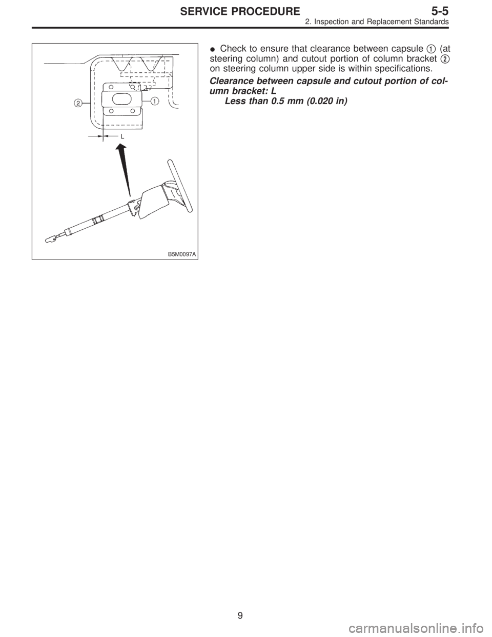
B5M0097A
�Check to ensure that clearance between capsule�1(at
steering column) and cutout portion of column bracket�
2
on steering column upper side is within specifications.
Clearance between capsule and cutout portion of col-
umn bracket: L
Less than 0.5 mm (0.020 in)
9
5-5SERVICE PROCEDURE
2. Inspection and Replacement Standards
Page 1666 of 3342
G5M0312
3) Remove lower cover.
Disconnect airbag connector (AB3) and (AB8) below steer-
ing column.
CAUTION:
Do not reconnect airbag connector at steering column
until front sensors are securely re-installed.
G5M0313
4) Remove console box. Discon-
nect 2-pin blue connector (AB4) (right side front sensor)
and 2-pin orange connector (AB5) (left side front sensor)
from airbag control module.
G5M0314
5) Roll up floor mat and side sill cover.
[W5A10].> Remove front sensor harness from clip and pro-
tector.
6) Remove front wheels.
7) Remove front mud guard.
G5M0315
8) Remove wiring harness clips.
G5M0316
9) Remove grommet.
14
5-5SERVICE PROCEDURE
4. Front Sensor
Page 1667 of 3342
B5M0102
10) Remove front sensor.
B: INSTALLATION
Installation is in reverse order of removal procedures.
5. Main Harness
A: REMOVAL
1) Turn ignition switch off.
2) Disconnect ground cable from battery and wait for at
least 20 seconds before starting work.
G5M0312
3) Remove lower cover.
Disconnect airbag connector (AB3) and (AB8) below steer-
ing column.
CAUTION:
Do not reconnect airbag connector at steering column
until main harness are securely re-installed.
G5M0313
4) Remove console box. Discon-
nect 12-pin yellow connector (AB6) from airbag control
module.
15
5-5SERVICE PROCEDURE
4. Front Sensor - 5. Main Harness
Page 1668 of 3342
B5M0102
10) Remove front sensor.
B: INSTALLATION
Installation is in reverse order of removal procedures.
5. Main Harness
A: REMOVAL
1) Turn ignition switch off.
2) Disconnect ground cable from battery and wait for at
least 20 seconds before starting work.
G5M0312
3) Remove lower cover.
Disconnect airbag connector (AB3) and (AB8) below steer-
ing column.
CAUTION:
Do not reconnect airbag connector at steering column
until main harness are securely re-installed.
G5M0313
4) Remove console box. Discon-
nect 12-pin yellow connector (AB6) from airbag control
module.
15
5-5SERVICE PROCEDURE
4. Front Sensor - 5. Main Harness
 Remove cover back panel.
G5M0278
8) Remove two bolts and lower steering column.
B5M0027
9) Set temperature control lever to Max. COLD position,
and then disconnect temperature control cable")
![SUBARU LEGACY 1997 Service Repair Manual G5M0312
3) Remove lower cover. <Ref. to 5-4 [W1A0].>
Disconnect airbag connector (AB3) and (AB8) below steer-
ing column.
CAUTION:
Do not reconnect airbag connector at steering column
until front sens](/manual-img/17/57434/w960_57434-1665.png "SUBARU LEGACY 1997 Service Repair Manual G5M0312
3) Remove lower cover. <Ref. to 5-4 [W1A0].>
Disconnect airbag connector (AB3) and (AB8) below steer-
ing column.
CAUTION:
Do not reconnect airbag connector at steering column
until front sens")
 Remove front sensor.
B: INSTALLATION
Installation is in reverse order of removal procedures.
5. Main Harness
A: REMOVAL
1) Turn ignition switch off.
2) Disconnect ground cable from battery")
 Remove front sensor.
B: INSTALLATION
Installation is in reverse order of removal procedures.
5. Main Harness
A: REMOVAL
1) Turn ignition switch off.
2) Disconnect ground cable from battery")