Page 2721 of 3342
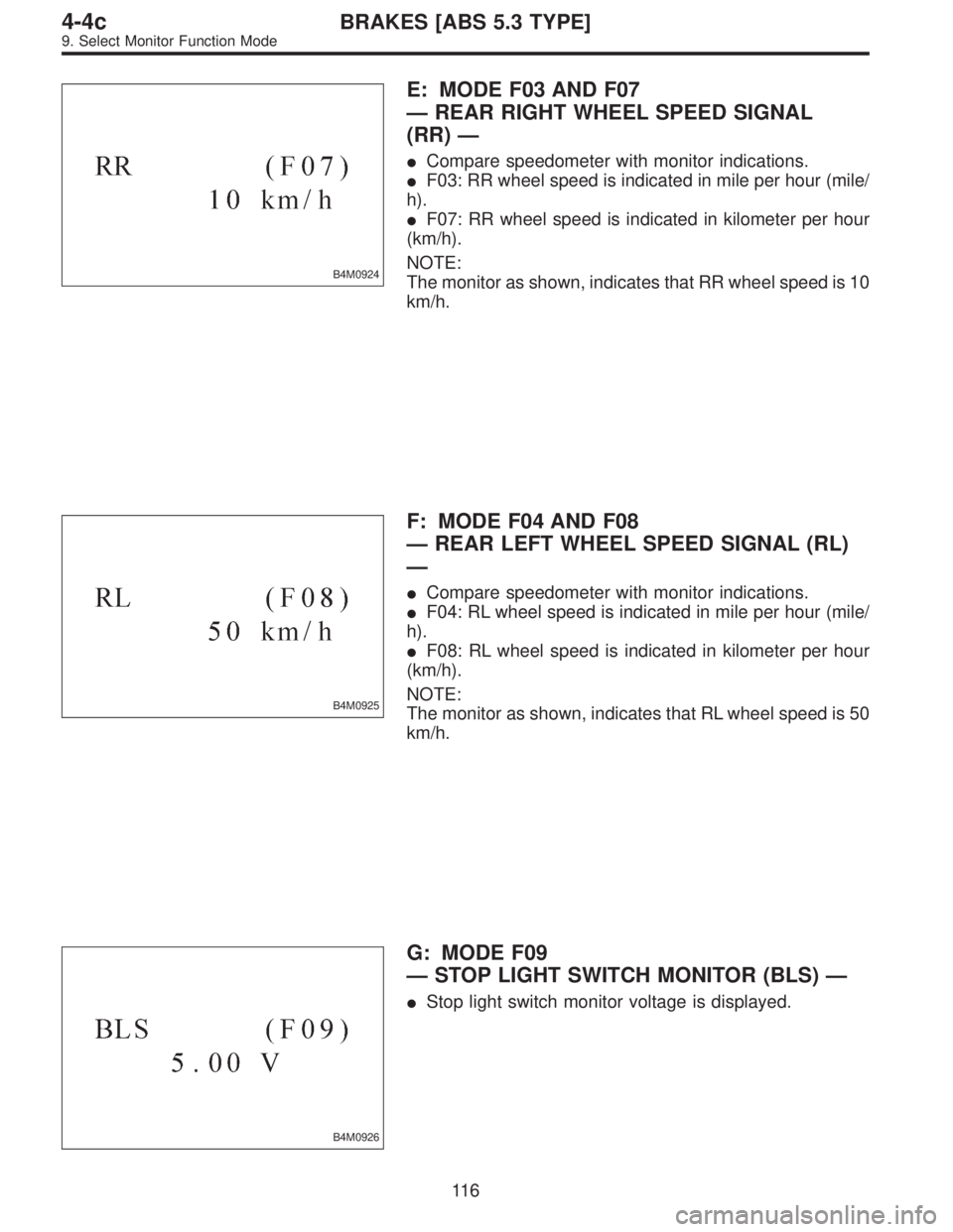
B4M0924
E: MODE F03 AND F07
—REAR RIGHT WHEEL SPEED SIGNAL
(RR)—
�Compare speedometer with monitor indications.
�F03: RR wheel speed is indicated in mile per hour (mile/
h).
�F07: RR wheel speed is indicated in kilometer per hour
(km/h).
NOTE:
The monitor as shown, indicates that RR wheel speed is 10
km/h.
B4M0925
F: MODE F04 AND F08
—REAR LEFT WHEEL SPEED SIGNAL (RL)
—
�Compare speedometer with monitor indications.
�F04: RL wheel speed is indicated in mile per hour (mile/
h).
�F08: RL wheel speed is indicated in kilometer per hour
(km/h).
NOTE:
The monitor as shown, indicates that RL wheel speed is 50
km/h.
B4M0926
G: MODE F09
—STOP LIGHT SWITCH MONITOR (BLS)—
�Stop light switch monitor voltage is displayed.
11 6
4-4cBRAKES [ABS 5.3 TYPE]
9. Select Monitor Function Mode
Page 2722 of 3342
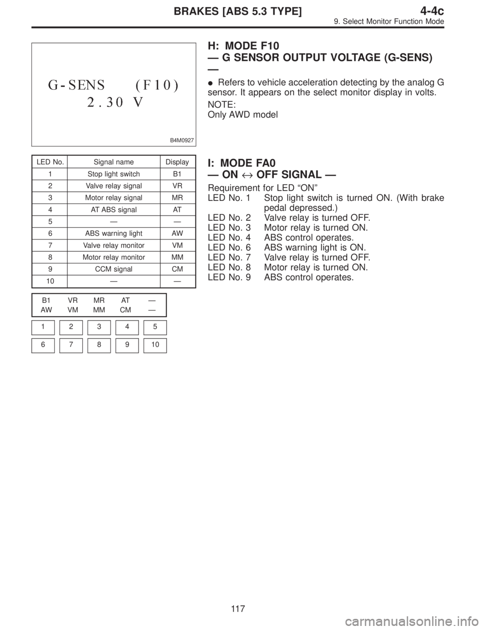
B4M0927
H: MODE F10
—G SENSOR OUTPUT VOLTAGE (G-SENS)
—
�Refers to vehicle acceleration detecting by the analog G
sensor. It appears on the select monitor display in volts.
NOTE:
Only AWD model
LED No. Signal name Display
1 Stop light switch B1
2 Valve relay signal VR
3 Motor relay signal MR
4 AT ABS signal AT
5——
6 ABS warning light AW
7 Valve relay monitor VM
8 Motor relay monitor MM
9 CCM signal CM
10——
B1 VR MR AT—
AW VM MM CM—
1
2345
678910
I: MODE FA0
—ON↔OFF SIGNAL—
Requirement for LED“ON”
LED No. 1 Stop light switch is turned ON. (With brake
pedal depressed.)
LED No. 2 Valve relay is turned OFF.
LED No. 3 Motor relay is turned ON.
LED No. 4 ABS control operates.
LED No. 6 ABS warning light is ON.
LED No. 7 Valve relay is turned OFF.
LED No. 8 Motor relay is turned ON.
LED No. 9 ABS control operates.
11 7
4-4cBRAKES [ABS 5.3 TYPE]
9. Select Monitor Function Mode
Page 2726 of 3342
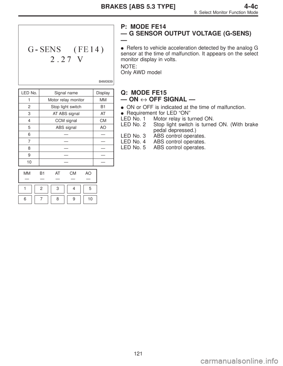
B4M0939
P: MODE FE14
—G SENSOR OUTPUT VOLTAGE (G-SENS)
—
�Refers to vehicle acceleration detected by the analog G
sensor at the time of malfunction. It appears on the select
monitor display in volts.
NOTE:
Only AWD model
LED No. Signal name Display
1 Motor relay monitor MM
2 Stop light switch B1
3 AT ABS signal AT
4 CCM signal CM
5 ABS signal AO
6——
7——
8——
9——
10——
MM B1 AT CM AO
—————
1
2345
678910
Q: MODE FE15
—ON↔OFF SIGNAL—
�ON or OFF is indicated at the time of malfunction.
�Requirement for LED“ON”
LED No. 1 Motor relay is turned ON.
LED No. 2 Stop light switch is turned ON. (With brake
pedal depressed.)
LED No. 3 ABS control operates.
LED No. 4 ABS control operates.
LED No. 5 ABS control operates.
121
4-4cBRAKES [ABS 5.3 TYPE]
9. Select Monitor Function Mode
Page 2728 of 3342
![SUBARU LEGACY 1997 Service Repair Manual B: LIST OF TROUBLE CODE
Code Display screen (FB1) Contents of diagnosis Ref. to
—ERROR 3 (1) Select monitor communication failure 4-4c [T10C0]
11 NO TROUBLEAlthough no trouble appears on the select](/manual-img/17/57434/w960_57434-2727.png "SUBARU LEGACY 1997 Service Repair Manual B: LIST OF TROUBLE CODE
Code Display screen (FB1) Contents of diagnosis Ref. to
—ERROR 3 (1) Select monitor communication failure 4-4c [T10C0]
11 NO TROUBLEAlthough no trouble appears on the select")
B: LIST OF TROUBLE CODE
Code Display screen (FB1) Contents of diagnosis Ref. to
—ERROR 3 (1) Select monitor communication failure 4-4c [T10C0]
11 NO TROUBLEAlthough no trouble appears on the select monitor display, the ABS
warning light remains on.4-4c [T10D0]
21 FR. SS HARD Open circuit or input voltage too high of FR sensor 4-4c [T10E0]
22 FR. SS SOFT Abnormal ABS sensor signal of FR sensor 4-4c [T10I0]
23 FL. SS HARD Open circuit or input voltage too high of FL sensor 4-4c [T10F0]
24 FL. SS SOFT Abnormal ABS sensor signal of FL sensor 4-4c [T10J0]
25 RR. SS HARD Open circuit or input voltage too high of RR sensor 4-4c [T10G0]
26 RR. SS SOFT Abnormal ABS sensor signal of RR sensor 4-4c [T10K0]
27 RL. SS HARD Open circuit or input voltage too high of RL sensor 4-4c [T10H0]
28 RL. SS SOFT Abnormal ABS sensor signal of RL sensor 4-4c [T10L0]
29 EITHER. SS SOFT Abnormal ABS sensor signal (any one of four) 4-4c [T10M0]
31 FR. EV VALVE Abnormal FR inlet valve 4-4c [T10N0]
32 FR. AV VALVE Abnormal FR outlet valve 4-4c [T10R0]
33 FL. EV VALVE Abnormal FL inlet valve 4-4c [T10O0]
34 FL. AV VALVE Abnormal FL outlet valve 4-4c [T10S0]
35 RR. EV VALVE Abnormal RR inlet valve 4-4c [T10P0]
36 RR. AV VALVE Abnormal RR outlet valve 4-4c [T10T0]
37 RL. EV VALVE Abnormal RL inlet valve 4-4c [T10Q0]
38 RL. AV VALVE Abnormal RL outlet valve 4-4c [T10U0]
41 ECU Abnormal ABSCM 4-4c [T10V0]
42 LOW VOLTAGE Source voltage is low. 4-4c [T10W0]
44CCM LINE A combination of AT control abnormals (ABS not in control) 4-4c [T10X0]
CCM OPEN A combination of AT control abnormals (ABS in control) 4-4c [T10Y0]
46GS POWER OVER G sensor line voltage too high 4-4c [T10Z0]
GS POWER LOW G sensor line voltage too low 4-4c [T10AA0]
51V. RELAY Abnormal valve relay 4-4c [T10AB0]
V. RELAY ON Valve relay ON failure 4-4c [T10AC0]
52M. RELAY OPEN Open circuit of motor relay 4-4c [T10AD0]
M. RELAY ON Motor relay ON failure 4-4c [T10AE0]
MOTOR Abnormal motor 4-4c [T10AF0]
54 BLS Abnormal stop light switch 4-4c [T10AG0]
56G SENSOR LINE Open or short circuit of G sensor 4-4c [T10AH0]
G SENSOR +B Battery short of G sensor 4-4c [T10AI0]
G SENSOR Hµ Abnormal G sensor high µ output 4-4c [T10AJ0]
G SENSOR STICK G sensor output is stuck. 4-4c [T10AK0]
NOTE:
High µ means high friction coefficient against road sur-
face.
123
4-4cBRAKES [ABS 5.3 TYPE]
10. Diagnostics Chart with Select Monitor
Page 2729 of 3342
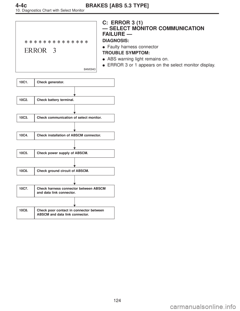
B4M0943
C: ERROR 3 (1)
—SELECT MONITOR COMMUNICATION
FAILURE—
DIAGNOSIS:
�Faulty harness connector
TROUBLE SYMPTOM:
�ABS warning light remains on.
�ERROR 3 or 1 appears on the select monitor display.
10C1.Check generator.
10C2.Check battery terminal.
10C3.Check communication of select monitor.
10C4.Check installation of ABSCM connector.
10C5.Check power supply of ABSCM.
10C6.Check ground circuit of ABSCM.
10C7.Check harness connector between ABSCM
and data link connector.
10C8.Check poor contact in connector between
ABSCM and data link connector.
�
�
�
�
�
�
�
124
4-4cBRAKES [ABS 5.3 TYPE]
10. Diagnostics Chart with Select Monitor
Page 2734 of 3342
B4M0944
D: NO TROUBLE
—ALTHOUGH NO TROUBLE APPEARS ON
THE SELECT MONITOR DISPLAY, THE ABS
WARNING LIGHT REMAINS ON.—
DIAGNOSIS:
�ABS warning light circuit is shorted.
TROUBLE SYMPTOM:
�ABS warning light remains on.
�NO TROUBLE displayed on the select monitor.
NOTE:
When the ABS warning light is OFF and“NO TROUBLE”
is displayed on the select monitor, the system is in normal
condition.
10D1.Check ground short of harness.
10D2.Check ground short of relay box.
�
129
4-4cBRAKES [ABS 5.3 TYPE]
10. Diagnostics Chart with Select Monitor
Page 2740 of 3342

B4M0922
10H1CHECK OUTPUT OF ABS SENSOR
USING SELECT MONITOR.
Read the ABS sensor output corresponding to the faulty
system in the select monitor function mode.
NOTE:
The select monitor display shows that the front right wheel
is rotating at 30 km/h.
: Does the speed indicated on the display
change in response to the speedometer
reading during acceleration/deceleration
when the steering wheel is in the straight-
ahead position?
: Go to step10H2.
: Go to step10H5.
10H2CHECK ABS SENSOR MECHANICAL
TROUBLE.
: Tightening torque:
32±10 N⋅m (3.3±1.0 kg-m, 24±7 ft-lb)
Are the ABS sensor installation bolts tight-
ened securely?
: Go to next.
: Tighten ABS sensor installation bolts securely.
: Tightening torque:
13±3 N⋅m (1.3±0.3 kg-m, 9±2.2 ft-lb)
Are the tone wheel installation bolts tight-
ened securely?
: Go to next step.
: Tighten tone wheel installation bolts securely.
G4M0700
1) Measure tone wheel-to-pole piece gap over entire
perimeter of the wheel.
: Is the gap within the specifications shown
in the following table?
SpecificationsFront wheel Rear wheel
0.9—1.4 mm
(0.035—0.055 in)0.7—1.2 mm
(0.028—0.047 in)
135
4-4cBRAKES [ABS 5.3 TYPE]
10. Diagnostics Chart with Select Monitor
Page 2749 of 3342

B4M0922
10L1CHECK OUTPUT OF ABS SENSOR
USING SELECT MONITOR.
Read the ABS sensor output corresponding to the faulty
system in the select monitor function mode.
NOTE:
The select monitor display shows that the front right wheel
is rotating at 30 km/h.
: Does the speed indicated on the display
change in response to the speedometer
reading during acceleration/deceleration
when the steering wheel is in the straight-
ahead position?
: Go to step10L2.
: Go to step10L3.
10L2CHECK POOR CONTACT IN CONNEC-
TOR BETWEEN ABSCM AND ABS SEN-
SOR.
: Is there poor contact in connectors between
ABSCM and ABS sensor?
: Repair connector.
: Go to step10L3.
10L3
CHECK SOURCES OF SIGNAL NOISE.
: Is the car telephone or the wireless trans-
mitter properly installed?
: Go to next.
: Properly install the car telephone or the wireless
transmitter.
: Are noise sources (such as an antenna)
installed near the sensor harness?
: Install the noise sources apart from the sensor
harness.
: Go to step10L4.
144
4-4cBRAKES [ABS 5.3 TYPE]
10. Diagnostics Chart with Select Monitor