Page 2331 of 3342
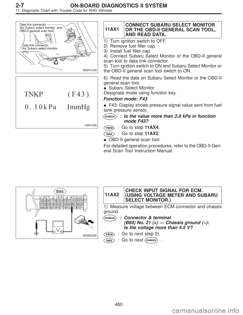
B2M1016A
11AX1CONNECT SUBARU SELECT MONITOR
OR THE OBD-II GENERAL SCAN TOOL,
AND READ DATA.
1) Turn ignition switch to OFF.
2) Remove fuel filler cap.
3) Install fuel filler cap.
4) Connect Subaru Select Monitor or the OBD-II general
scan tool to data link connector.
5) Turn ignition switch to ON and Subaru Select Monitor or
the OBD-II general scan tool switch to ON.
H2M1326
6) Read the data on Subaru Select Monitor or the OBD-II
general scan tool.
�Subaru Select Monitor
Designate mode using function key.
Function mode: F43
�F43: Display shows pressure signal value sent from fuel
tank pressure sensor.
: Is the value more than 2.8 kPa in function
mode F43?
: Go to step11AX4.
: Go to step11AX2.
�OBD-II general scan tool
For detailed operation procedures, refer to the OBD-II Gen-
eral Scan Tool Instruction Manual.
B2M0535A
11AX2CHECK INPUT SIGNAL FOR ECM.
(USING VOLTAGE METER AND SUBARU
SELECT MONITOR.)
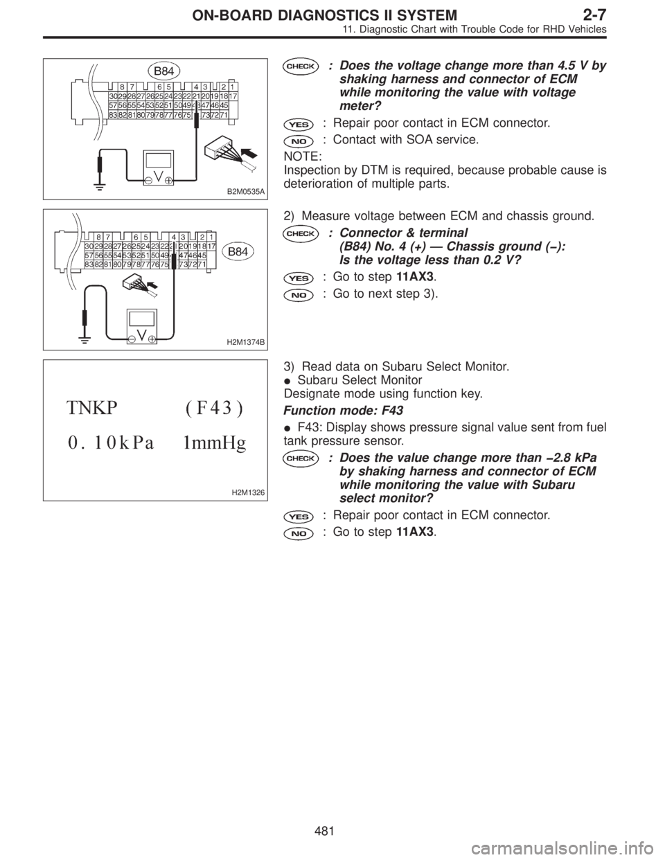
1) Measure voltage between ECM connector and chassis
ground.
: Connector & terminal
(B84) No. 21 (+)—Chassis ground (�):
Is the voltage more than 4.5 V?
: Go to next step 2).
: Go to next.
480
2-7ON-BOARD DIAGNOSTICS II SYSTEM
11. Diagnostic Chart with Trouble Code for RHD Vehicles
Page 2332 of 3342
B2M0535A
: Does the voltage change more than 4.5 V by
shaking harness and connector of ECM
while monitoring the value with voltage
meter?
: Repair poor contact in ECM connector.
: Contact with SOA service.
NOTE:
Inspection by DTM is required, because probable cause is
deterioration of multiple parts.
H2M1374B
2) Measure voltage between ECM and chassis ground.
: Connector & terminal
(B84) No. 4 (+)—Chassis ground (�):
Is the voltage less than 0.2 V?
: Go to step11AX3.
: Go to next step 3).
H2M1326
3) Read data on Subaru Select Monitor.
�Subaru Select Monitor
Designate mode using function key.
Function mode: F43
�F43: Display shows pressure signal value sent from fuel
tank pressure sensor.
: Does the value change more than�2.8 kPa
by shaking harness and connector of ECM
while monitoring the value with Subaru
select monitor?
: Repair poor contact in ECM connector.
: Go to step11AX3.
481
2-7ON-BOARD DIAGNOSTICS II SYSTEM
11. Diagnostic Chart with Trouble Code for RHD Vehicles
Page 2394 of 3342
11CP1CHECK DTC P0461, P0462 OR P0463 ON
DISPLAY.
: Does the Subaru select monitor or OBD-II
general scan tool indicate DTC P0461,
P0462 or P0463?
: Inspect DTC P0461, P0462 or P0463 using“11 .
Diagnostics Chart with Trouble Code”.
2-7 [T11A0].>
NOTE:
In this case, it is not necessary to inspect this trouble.
: Replace fuel sending unit and fuel sub meter unit.
543
2-7ON-BOARD DIAGNOSTICS II SYSTEM
11. Diagnostic Chart with Trouble Code for RHD Vehicles
Page 2416 of 3342
B: ABNORMAL DISPLAY ON AT OIL TEMP
INDICATOR
When any on-board diagnostic item is malfunctioning, the
display on the AT OIL TEMP indicator blinks immediately
after the engine starts.
The malfunctioning part or unit can be determined by a
trouble code during on-board diagnostic operation. Prob-
lems which occurred previously can also be identified
through the memory function.
If the AT OIL TEMP indicator does not show a problem
(although a problem is occurring), the problem can be
determined by checking the performance characteristics of
each sensor using the select monitor.
Indicator signal is as shown in the figure.
WARNING:
Warning can be noticed only when the engine is ini-
tially started.
B3M0410A
12
3-2AUTOMATIC TRANSMISSION AND DIFFERENTIAL
6. Diagnostic Chart for On-board Diagnostic System
Page 2419 of 3342
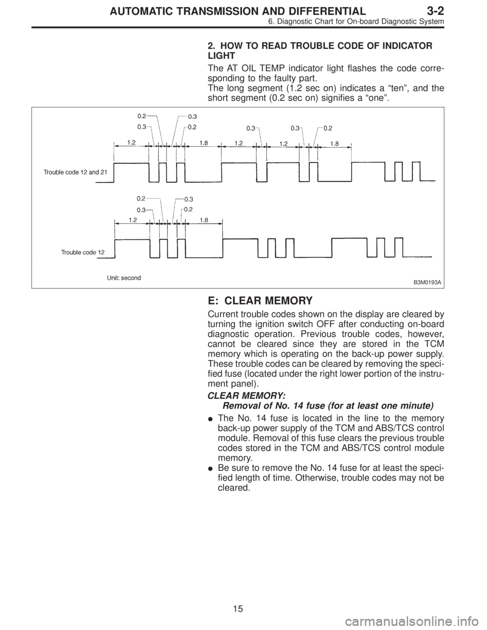
2. HOW TO READ TROUBLE CODE OF INDICATOR
LIGHT
The AT OIL TEMP indicator light flashes the code corre-
sponding to the faulty part.
The long segment (1.2 sec on) indicates a“ten”, and the
short segment (0.2 sec on) signifies a“one”.
B3M0193A
E: CLEAR MEMORY
Current trouble codes shown on the display are cleared by
turning the ignition switch OFF after conducting on-board
diagnostic operation. Previous trouble codes, however,
cannot be cleared since they are stored in the TCM
memory which is operating on the back-up power supply.
These trouble codes can be cleared by removing the speci-
fied fuse (located under the right lower portion of the instru-
ment panel).
CLEAR MEMORY:
Removal of No. 14 fuse (for at least one minute)
�The No. 14 fuse is located in the line to the memory
back-up power supply of the TCM and ABS/TCS control
module. Removal of this fuse clears the previous trouble
codes stored in the TCM and ABS/TCS control module
memory.
�Be sure to remove the No. 14 fuse for at least the speci-
fied length of time. Otherwise, trouble codes may not be
cleared.
15
3-2AUTOMATIC TRANSMISSION AND DIFFERENTIAL
6. Diagnostic Chart for On-board Diagnostic System
Page 2459 of 3342
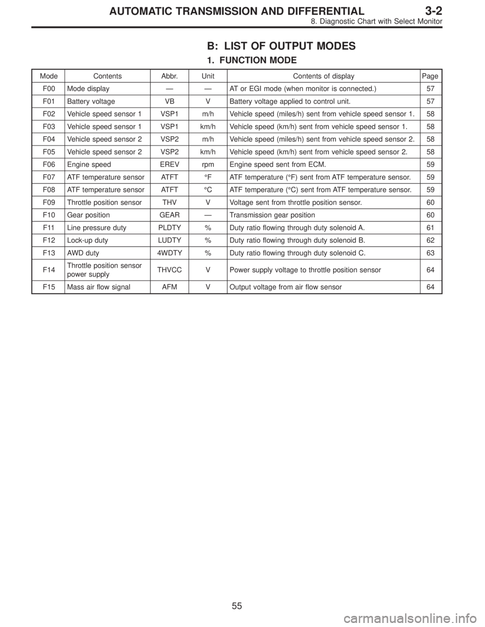
B: LIST OF OUTPUT MODES
1. FUNCTION MODE
Mode Contents Abbr. Unit Contents of display Page
F00 Mode display——AT or EGI mode (when monitor is connected.) 57
F01 Battery voltage VB V Battery voltage applied to control unit. 57
F02 Vehicle speed sensor 1 VSP1 m/h Vehicle speed (miles/h) sent from vehicle speed sensor 1. 58
F03 Vehicle speed sensor 1 VSP1 km/h Vehicle speed (km/h) sent from vehicle speed sensor 1. 58
F04 Vehicle speed sensor 2 VSP2 m/h Vehicle speed (miles/h) sent from vehicle speed sensor 2. 58
F05 Vehicle speed sensor 2 VSP2 km/h Vehicle speed (km/h) sent from vehicle speed sensor 2. 58
F06 Engine speed EREV rpm Engine speed sent from ECM. 59
F07 ATF temperature sensor ATFT°F ATF temperature (°F) sent from ATF temperature sensor. 59
F08 ATF temperature sensor ATFT°C ATF temperature (°C) sent from ATF temperature sensor. 59
F09 Throttle position sensor THV V Voltage sent from throttle position sensor. 60
F10 Gear position GEAR—Transmission gear position 60
F11 Line pressure duty PLDTY % Duty ratio flowing through duty solenoid A. 61
F12 Lock-up duty LUDTY % Duty ratio flowing through duty solenoid B. 62
F13 AWD duty 4WDTY % Duty ratio flowing through duty solenoid C. 63
F14Throttle position sensor
power supplyTHVCC V Power supply voltage to throttle position sensor 64
F15 Mass air flow signal AFM V Output voltage from air flow sensor 64
55
3-2AUTOMATIC TRANSMISSION AND DIFFERENTIAL
8. Diagnostic Chart with Select Monitor
Page 2460 of 3342
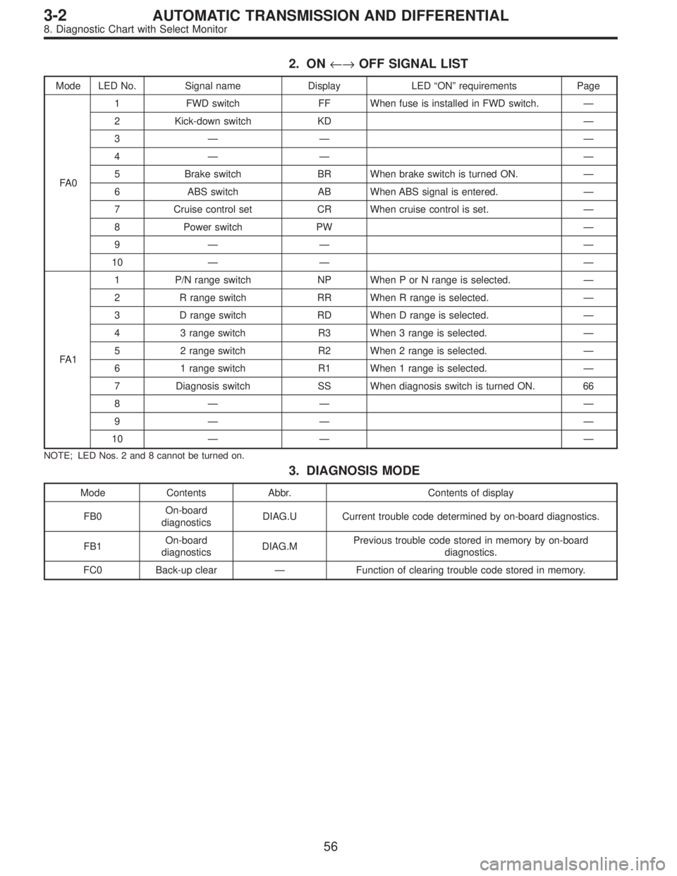
2. ON←→OFF SIGNAL LIST
Mode LED No. Signal name Display LED“ON”requirements Page
FA 01 FWD switch FF When fuse is installed in FWD switch.—
2 Kick-down switch KD—
3—— —
4—— —
5 Brake switch BR When brake switch is turned ON.—
6 ABS switch AB When ABS signal is entered.—
7 Cruise control set CR When cruise control is set.—
8 Power switch PW—
9—— —
10—— —
FA 11 P/N range switch NP When P or N range is selected.—
2 R range switch RR When R range is selected.—
3 D range switch RD When D range is selected.—
4 3 range switch R3 When 3 range is selected.—
5 2 range switch R2 When 2 range is selected.—
6 1 range switch R1 When 1 range is selected.—
7 Diagnosis switch SS When diagnosis switch is turned ON. 66
8—— —
9—— —
10—— —
NOTE; LED Nos. 2 and 8 cannot be turned on.
3. DIAGNOSIS MODE
Mode Contents Abbr. Contents of display
FB0On-board
diagnosticsDIAG.U Current trouble code determined by on-board diagnostics.
FB1On-board
diagnosticsDIAG.MPrevious trouble code stored in memory by on-board
diagnostics.
FC0 Back-up clear—Function of clearing trouble code stored in memory.
56
3-2AUTOMATIC TRANSMISSION AND DIFFERENTIAL
8. Diagnostic Chart with Select Monitor
Page 2461 of 3342
B3M0639
C: MODE F00—MODE DISPLAY—
SPECIFIED DATA:
Data at the left should be indicated.
Probable cause (if outside“specified data”)
1. Communication failure
(No communication method can be confirmed
with power ON.)
�(1)Check loose or poor connectors, or
shortcircuit.
(2) Check type of cartridge.
2. Vehicle types cannot be identified (due to
communication failure).�Check improper cartridge.
Replace with proper one.
G3M0724
D: MODE F01—BATTERY VOLTAGE (VB)—
CONDITION:
�Ignition switch ON
�Engine idling after warm-up
SPECIFIED DATA:
VB: 10—16 V
1. Battery�Check battery voltage and specific gravity of
electrolyte.
2. Charging system�(1)Measure regulating voltage under no loads.
(2) Check generator (as a single unit).
57
3-2AUTOMATIC TRANSMISSION AND DIFFERENTIAL
8. Diagnostic Chart with Select Monitor